The Main Menu is where all the domain-related settings, such as domain size, variables solved, physical properties, numerical and output controls are set. Any source which operates over the whole domain is also set from here.
The main menu is reached by:
All these methods bring up the Main Menu top panel.
This is the top panel of the main menu, and can be reached from any other panel by clicking on Top menu. It is the panel displayed whenever the Main menu is activated from the hand-set, and it is the only panel from which it is possible to return to the main VR-Editor environment.
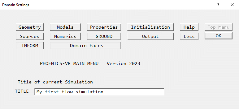
Image: TOP PANEL
From the Top menu panel, a Title can be set for the current case. This is a text string up to 40 characters long, which then appears in all the input and output files.
The buttons along the top of the panel allow the setting and modification of the case. In general, it is best to start at the top left, and work from left to right, top row then bottom row, as this minimises the chances of missing out settings.
The (show) 'Less' button is special, in that when pressed it changes to (show) 'More', and all the menu panels show only the most commonly used options. This mode is aimed at beginners and in-frequent users, who do not wish to be swamped with options they may not need. All the images of menu panels are in the full (show) 'more' mode. The mode is recorded in the Q1 file saved at the end of the session, and hence will be used next time the Q1 is loaded.
The buttons perform the following functions:
The Help button on each panel gives a more detailed overview of the functions available from that panel - it links to the relevant section of this document.
Help on individual data-entry boxes and buttons can be obtained by clicking on the '?' in the top-right of the window, and then clicking on the required item.
Some panels contain more lines than can be shown. In such at case, a Page Dn and Line Dn button will appear at the bottom of the panel. These scroll the panel down by a page or a single line to reveal the remaining options. The font and screen resolution influence this, so the menu panels may not appear exactly as depicted here.
The In-Form editor allows commands in the In-Form language to be added to the model. In-Form allows the specification of:
by way of formulae placed in the data-input file. The In-Form editor provides a simple interactive means of creating and modifying the formulae.
Clicking the 'INFORM' button on the Top Menu panel brings up a dialog which allows you to select which Inform Save block to create or open.
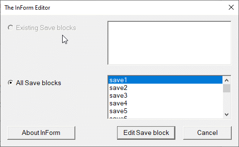
Image: The In-Form Editor Save block Selector
Once a Save block has been selected, 'Edit Save block' will open a file editor to edit the Save block.
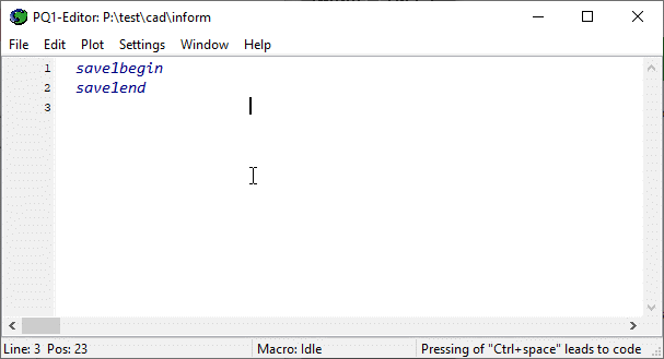
Image: The In-Form Editor
The Inform commands should be entered between the 'save begin' and 'save end' lines, starting in column 1 or 2. Comment lines can be inserted starting in column 3 or more, or after a ! symbol. The 'save begin / end' lines must be in column 3 or more.
When the Q1 is saved, each Save block is written to the corresponding Group of the Q1.
Full details can be found in INFORM: TR 003.
To delete an existing save block, select it from the 'Existing save blocks' list and click 'Edit Save block'. In the file editor delete the entire block including the 'save begin' and 'save end' lines, then save and exit. The block will no longer appear in the 'Existing blocks' list and will re-appear in the 'All Save blocks' list.
Clicking on this button brings up a dialog from which boundary conditions can be applied to entire domain faces.
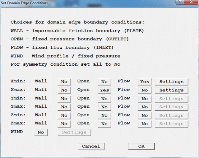
Xmin, Xmax, Ymin, Ymax, Zmin, Zmax denote the opposite faces of the domain in the X, Y and Z directions. The available options are:
These objects will appear on the screen, and will be listed in the Object Management Panel. The default names for these objects can be changed from the Object Specification dialogs as for any other object.
At a face, these options are mutually exclusive - selecting one will deselect any other selection. The objects are created with default attributes. The user must ensure that any non-default values, such as an inlet velocity or wall surface temperature, are set by opening the attribute dialogs for these objects and setting any required values.
Any PLATE, OUTLET or INLET objects which cover the entire face of the domain will be recognised as domain-face, and will cause the appropriate flags to be set to Yes on the above dialog.
For external wind-driven flows it will often be much easier to activate the WIND object.
The function of the WIND object is to provide boundary conditions representing the atmospheric boundary layer due to the wind at all faces of the domain in a self-consistent manner. The following conditions are applied:
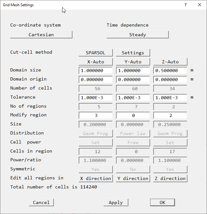
Image: GEOMETRY
For Cartesian and Polar co-ordinates, this is the same dialog that is displayed by
clicking on the Grid mesh ![]() button on the hand-set, then clicking on the mesh region to be
changed. Region 1 in each direction is initially selected. Descriptions of how to modify
the mesh are given in VR-Editor
Hand-set, Mesh Toggle, and in Space
and Time grids.
button on the hand-set, then clicking on the mesh region to be
changed. Region 1 in each direction is initially selected. Descriptions of how to modify
the mesh are given in VR-Editor
Hand-set, Mesh Toggle, and in Space
and Time grids.
The settings are:
For Body-Fitted Co-ordinates, changes to the grid are made in the BFC menu.
This panel controls the variables to be solved, and the models used.
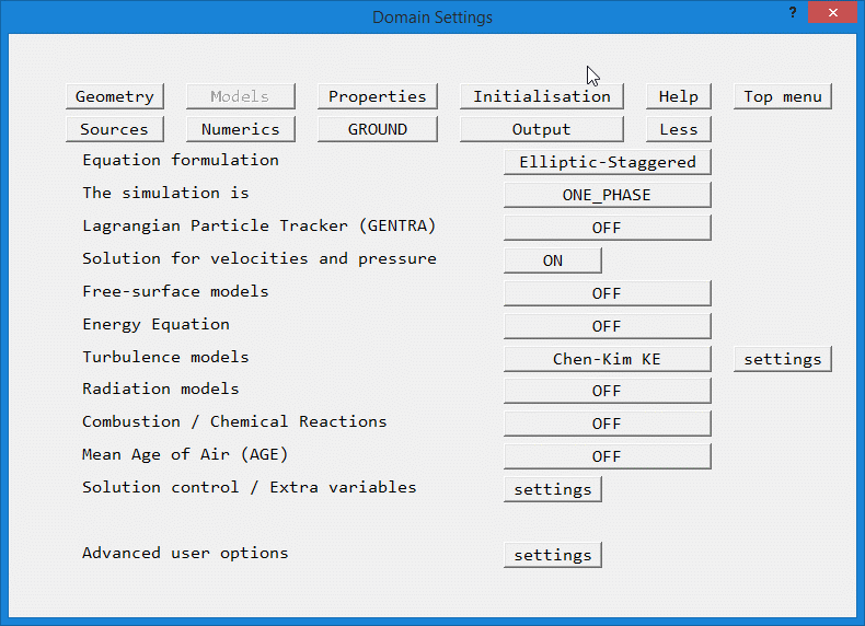
Image: MODELS
Equation formulation
, Simulation is, Lagrangian Particle Tracker (GENTRA), Solution for velocities and pressure, Free-surface models, Energy equation, Turbulence models, Radiation models, Combustion Models, Mean Age of Air, Solution control / Extra variables, Advanced user OptionsThis allows the formulation of the equations to be chosen. The options are:
The main choice is between elliptic, parabolic and fully-developed. Elliptic is the most usual form, as it allows for recirculation.
There is a further choice of staggered or collocated velocity formulation. In the staggered formulation, velocities are stored at cell face centres, in the collocated form they are stored at cell centres, just like pressure and temperature.
The staggered form is usually best for Cartesian and polar grids, the GCV collocated for BFC. See also the CCM entry in the PHOENICS Encyclopaedia.
Parabolic performs a marching integration suitable for flows with no recirculation, e.g. developing pipe flows or jet spreading.
Fully-developed calculations will give the flow rate for a given pressure-drop, or the pressure-drop for a given flow, without any information on how the flow developed.
This option switches between single and multi-phase operation. If the domain is occupied by a single fluid, which does not change phase, or by several fluids which ARE ALWAYS SEPARATED by solid, the flow can be treated as single phase. If the fluid changes phase, or there are several MIXED fluids, then the flow must be treated as multi-phase.
The available options are:
The Encyclopaedia entry on Multi-phase flow gives more details.
This activates the GENTRA Lagrangian particle tracker, which is described in The Gentra User Guide TR/211. The particle tracker is an alternative way of treating multi-phase flows. It is suitable for dilute suspensions, where volume-fraction effects are small. Packets of particles are tracked through the domain. Each packet represents a large number of particles following this path. The particles can exchange heat, mass and momentum with the carrier fluid.
This option switches ON or OFF the solution for the pressure variable P1, and the velocities U1, V1 and W1 (depending on the dimensionality of the problem). If the simulation is two-phase, then the second phase velocities U2, V2 and W2 will also be activated. If the grid dimensionality is changed later, the required velocity component( s) will be added or removed as needed.
Pressure and velocity must be ON before it becomes possible to select Multi-Phase or Free-Surface models.
If the geometry is axi-symmetrical (two dimensional in the Y-Z plane), this option switches on the solution for the swirl component of velocity. (This button is only present for cylindrical-polar geometries.)
The available free surface models are:
VOF retains the sharpness of the interface well.
The Scalar Equation Method (SEM) is a simplified VOF which does not preserve the interface so well, but may run slightly faster.
Both VOF and SEM are good for overturning or breaking interfaces, but are restricted to very small time steps.
The VOF schemes, especially STACS can tolerate bigger time steps than SEM.
Height of Liquid (HOL) can run steady-state, or with larger time steps but cannot deal with overturning interfaces.
See also the POLIS entries on Volume of Fluid and Scalar Equation Method and Height of Liquid.
The energy equation can be solved in one of two forms:
The enthalpy form is often more suited to combustion applications, the temperature form to conjugate heat transfer. Internally, the equation is always cast in enthalpy form, so the units of the sources are always Watts.
By default, the Temperature form is set to 'Total', the enthalpy form to 'Static'. The static form includes the substantial derivative of the pressure and the kinetic heating terms in the energy conservation equation as additional source terms, the Total form does not.
If the flow is highly compressible (high Mach number) the Temperature form should be switched to 'Static' otherwise incorrect solutions will be obtained. This is because all the property formulae require the static temperature.
The Enthalpy form can be used in 'Total' form as long as a suitable temperature derivation is selected in the properties panel.
The available turbulence models are divided into the following groups:
All models are described in the POLIS Encyclopaedia under ' Turbulence', where each has its own descriptive article.
Brief advice: use the simplest model which produces realistic results. In many cases, the CHEN-KIM model provides a reasonable compromise between accuracy and economy. If there are many walls (obstacles) present, the LVEL model will be even more economical, and also more accurate for coarse grids.
The following radiation models are available:
They are described in full in the PHOENICS Encyclopaedia under ' Radiative Heat Transfer in PHOENICS'.
WARNING: The 6-Flux and Radiosity models are not fully implemented in the Menu, especially with regard to the boundary conditions or conjugate heat transfer. Please use the ' User-defined' object attribute to set the boundary conditions described in POLIS. The IMMERSOL and P-1 T3 models are fully implemented.
The following combustion models are available:
They are described in the PHOENICS Encyclopaedia under: ' Combustion', ' Reaction', ' SCRS', ' Extended Simple Chemically-reacting System',' CHEMKIN Interface'. There are examples in the 'Chemical-reaction library'.
WARNING: Only the 3_GASES model is fully implemented in the Menu. The remaining models are not yet implemented in the Menu. Solution of the required variables can be activated through the Solution control - Extra variables button below.
Please use the 'User-defined' object attribute to set the boundary conditions described in POLIS.
The AGE variable represents an estimate of the 'time since entry'. It is obtained by solving for a tracer, named AGE, which has a uniform source of 1/m3/s, and is zero at all inflow boundaries. If the flow were one-dimensional and steady, AGE would be equal to the time spent by local air particles in traveling from the entrance to the point in question.
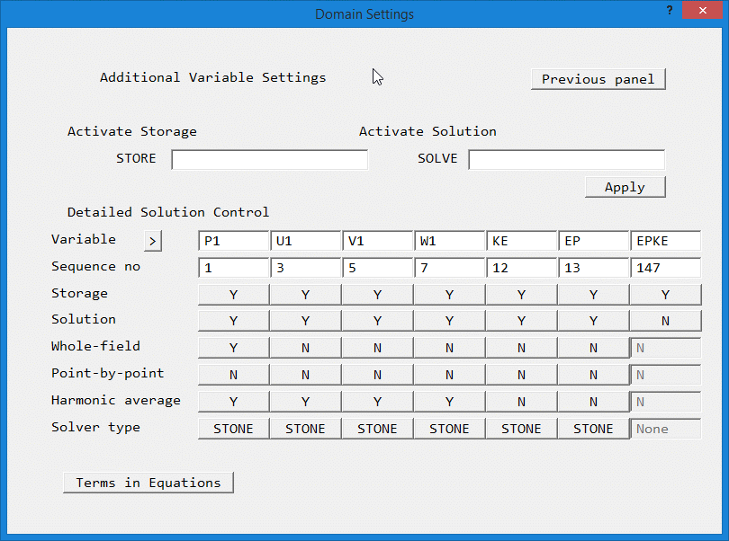
Image: SOLUTION CONTROL / EXTRA VARIABLES
This panel gives options to:
See the POLIS Encyclopaedia entries on SOLUTN and TERMS for more information.
This panel gives access to PIL settings from Groups 7 and 8 which are not covered by the other sub-menus of this panel.
From this panel, the main domain material can be chosen from the CHAM-supplied property libraries.
The domain material is the material that initially fills the entire solution domain. Regions of the domain can then be filled with other fluids or solids by creating BLOCKAGE objects, and selecting the required material for them.
The individual properties loaded from the library for the domain fluid can then be edited - changed. This is not possible for the properties used for blockages. If a blockage is assigned the ' domain material', it will automatically pick up the properties specified here.
The reference pressure and temperature values are always added to the calculated pressure and temperature before use in property calculations. The reference temperature is set by choosing Centigrade (reference temperature is 273.15) or Kelvin (reference temperature is 0) for 'Temperature units'.
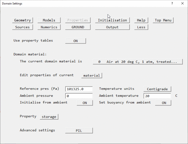
Image: PROPERTIES using Property Tables
The 'Ambient pressure' and 'Ambient temperature' entries set the pressure and temperature prevailing outside the domain. These values can be used, if desired, to set the pressure and temperature at all INLET, WIND, WIND_PROFILE, OUTLET, FAN and PRESSURE_RELIEF objects.
When 'Initialise from ambient' is set ON (the default), the initial values of pressure (P1) and temperature (TEM1) are always made consistent with the ambient values set here.
When 'Set buoyancy from ambient' is ON (the default), the reference temperature for Boussinesq buoyancy is set to the ambient temperature, or for density_difference buoyancy, the reference density is calculated from the ambient pressure and temperature.
The 'Property storage' button allows the field values of the properties to be placed in the EARTH output file PHI, so that they can be plotted in the viewer.
Turning the property tables OFF allows the individual properties to be set directly.
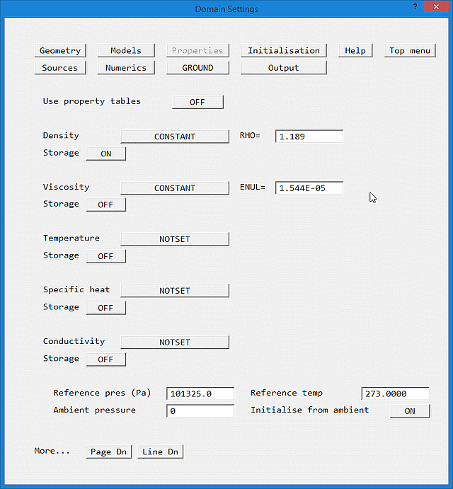
Image: PROPERTIES not using Property Tables
This panel is also accessed from the Edit properties of current material button on the previous figure. For each property, a pull-down list of all available options is provided. The available options are listed in Encyclopaedia.
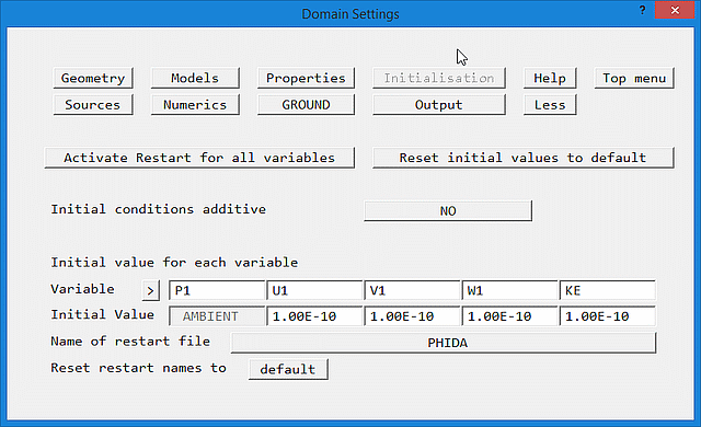
Image: INITIALISATION
This panel provides options to:
Unless explicitly set in this panel (or set to ambient), initial values for Temperature, Enthalpy, turbulence model quantities and solved-for passive scalars will be taken from the inlet values supplied at the first inlet defined.
NB. When solving for passive scalars where there is one inlet with a finite inlet value and one or more inlets or outlets with a value of 0.0 it can be important to set the initial value explicitly to 0.0, in case the domain is initialised to the finite inlet value.
If the inlet value of a scalar is 1.0, but the majority of the domain is filled with scalar=0.0, it is very important to explicitly initialise the relevant scalar(s) to zero.
If there are more than five stored/solved variables, the > (and <) buttons can be used to scroll through all available variables.
Although the names of the restart and cut-cell files may be displayed as upper-case, the Earth solver will convert them to lower-case.
If 'Restart cut-cell values' is set to NO, the values in the cut cells will retain their initial values as set here on restart, and the named file will not be read. This is useful when restarting a PARSOL=T run from a PARSOL=F run when the pbcl.dat file will be empty. It can also help avoid problems restarting parallel runs when the processors cannot agree on how many cut cells there are.
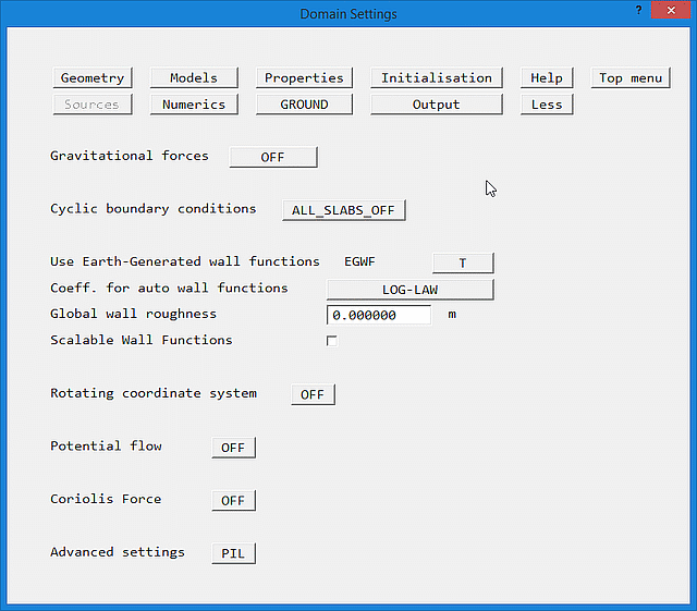
Image: SOURCES Panel
This panel allows the creation of whole-domain sources, which are not attached to an object. All sources or boundary conditions which do not apply to the whole domain must be attached to an object, and set through the appropriate object attribute dialog box.
The 'Cyclic boundary conditions' button gives the options:
Cyclic boundaries are then imposed between the first and last rows of cells in the IX direction, for the slabs indicated.
The MOFOR ON/OFF button (which only appears for Transient cases) activates the Moving Frames Of Reference model, which allows objects to move through the domain. When turned ON, two extra buttons are displayed. One allows the user to browse for the MOF file, and the other to edit it using the currently-selected file editor. The MOF file controls the motion of the objects. For more details, click here.
Use Earth-Generated Wall Functions when set to T causes the Earth solver to apply wall function boundary conditions on all exposed faces of all solids without the need for any explicit PATCH commands.
Coeff. for auto wall functions. This selects the type of turbulent wall function used to calculate shear stress and heat transfer on PLATE and BLOCKAGE objects. The options are:
Option 2 is the default. Option 3 will give better heat transfer coefficients at re-attachment points. Option 4 is suitable for atmospheric boundary layers.
Global wall roughness
For the Log-Law and general log-law wall functions, this is the absolute 'sand-grain roughness' size for rough walls, according to the formula of Nikuradse.
Typical values of sand-grain size for pipe materials are:
Copper, brass        0.0000305 - 0.0009
Wrought iron, steel  0.000046 - 0.0024
Asphalted cast iron  0.0001 - 0.0021
Galvanised iron      0.000102 - 0.0046
Cast iron            0.0002 - 0.0055
Concrete             0.0003 - 0.003
Uncoated cast iron   0.000226
Coated cast iron     0.000102
Coated spun iron     0.000056
Cement               0.0004 - 0.0012
Wrought iron         0.00005
Uncoated steel       0.000028
Coated steel         0.000058
Wood stave           0.0002 - 0.0009
PVC                  0.0000015
For fully-rough wall functions, it is the effective roughness height. Typical values of effective roughness height are:
Open flat terrain, grass, few isolated obstacles 0.03
Open sea                                         0.0002
Low crops, occasional large obstacles            0.10
High crops, scattered obstacles                  0.25
Parkland, bushes, numerous obstacles             0.50
Suburb, forest, regular large obstacle coverage  0.50 to 1.0
This value is used for all blockages, and all plates which do not have their own value set.
Note in Flair, the use of the fully-rough wall function is restricted to TERRAIN, BLOCKAGE and PLATE objects, and it does not appear in this list. It is the default wall function for the ground plane of the WIND object, and for TERRAIN objects.
Scalable Wall functions. The scalable wall function attempts to prevent the deterioration of wall shear-stress accuracy as the mesh is refined.
In wall cells the Y+ values are prevented from falling below the critical value of Y+c. The wall shear stress is calculated as if Y+ was Y+c.
The critical Y+ can be set in 'Turbulence models', 'Settings'. The default value is 11.126.
The panel also allows built-in whole-field sources to be set, such as:
The following buoyancy options are available
- Constant
- Density_difference
- Boussinesq Approximation
- Linear_in_2_scalars
All are described in the Encyclopaedia under 'Gravitational body forces'. In brief:
Option 1 applies the full gravitational force; this option should be avoided if at all possible as it requires the setting of appropriate vertical pressure gradients at all fixed pressure boundaries.
Option 2 uses a reference density, and should be used if the density is not constant;
Option 3 uses a reference temperature, and should be used if the density is constant but the temperature is variable
Option 4 allows the buoyancy force to be a function of any two solved scalars.
If 'Set buoyancy from ambient' on the Properties panel is set to ON, the values needed for Options 2 and 3 will be taken from the ambient temperature and pressure set there.
To create a new whole-field source click on 'Advanced settings PIL'. If this is not visible ,click on 'Page down' to show the next page of options.
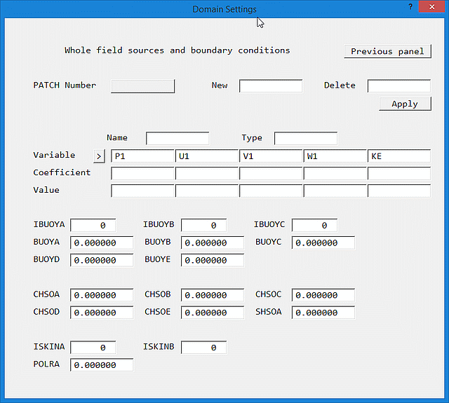
Image: WHOLE FIELD SOURCES
Enter the name of the PATCH in the 'New' box and click 'Apply'. A new PATCH will be created; the Type, Coefficient and Value can now be set as required. Clicking on PATCH number will cycle through the available Patches. The > (and <) symbol next to Variable scrolls through the list of available variables, if there are more than five.
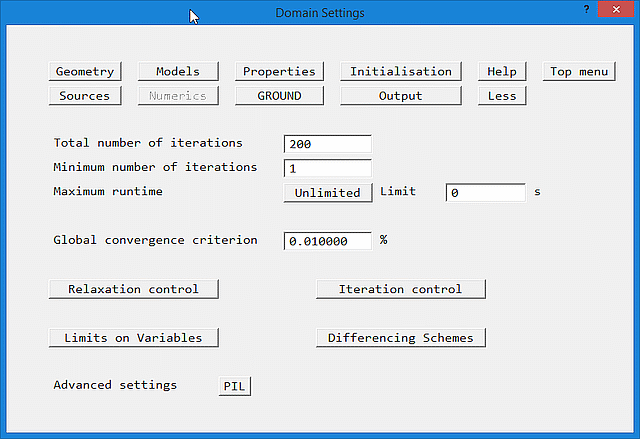
Image: NUMERICS
The main entries on this panel allow the total number of iterations ( sweeps) over the whole domain, and the global convergence criterion to be set.
In transient cases, the 'Vary with time' button leads to a dialog from which the number of sweeps per time step can be changed with time or time step. Up to 15 bands of sweep settings can be made. If more are required, or the conditions for variation are more complex InForm can be used.
The submenus give options to:
Numerics - Relaxation Settings
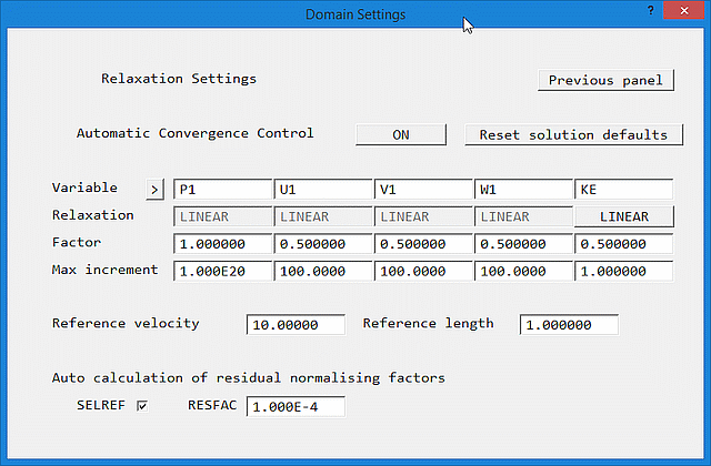
Image: Default RELAXATION SETTINGS
Relaxation is a technique for slowing down possibly excessive rates of change. It does not affect the final solution. In many cases, convergence will be very hard to obtain without suitable relaxation settings. The relaxation methods available are described in the Encyclopaedia article on RELAX.
The default relaxation settings turn the Automatic Convergence Control (CONWIZ=T in the Q1) ON.
Factor sets the relaxation factor for the variable in question. When Automatic ConvergenceControl is ON, only linear relaxation can be used for Pressure and velocity. For the remaining scalars, false-time step relaxation can be used, though usually linear is preferred.
Max increment sets the maximum increment (change) from iteration to iteration for each variable.
Reference velocity sets a typical velocity in the domain (usually based on a typical inlet velocity)
Reference length is a typical length scale for the case, usually based on the domain size.
The two reference quantities are used to estimate an initial timescale. In many cases, the default values work quite well. For large-scale external aerodynamics, for example flow over a city, where the domain may be kilometers in size it can be very important to set the reference length to an average domain size otherwise convergence may be unacceptably slow. The WIND object will do this automatically, otherwise the user should do so manually.
In this mode, any false time step settings for velocities are ignored - the solver will set linear relaxation of 0.5 for all velocities that have false time step relaxation. If the relaxation for velocities is switched to LINEAR, the user-set values will be used.
If no settings are made for the other variables, the solver will set linear relaxation of 0.5, except Temperature (TEM1) which is set to 0.25.
For fire simulations, the maximum increment for temperature (TEM1) should be reduced from the default value of 50°/sweep to, say, 10°/sweep, otherwise convergence may still be difficult. If the expected velocities are very small, the maximum increments for the velocity components should also be reduced. If a FIRE object (only available in FLAIR) is detected, and the relaxation for TEM1 is the default (no user setting has been made), the maximum increment for Temperature is automatically reduced to 10°/sweep.
'Reset solution defaults' resets all the solver control variables to their default values, so that the Automatic Convergence Control can operate in full.
If the Automatic Convergence Control is turned off, the relaxation settings can be set individually.
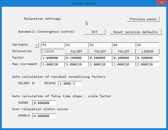
Image: Manual RELAXATION SETTINGS
Typical values for false time step relaxation may be estimated from the governing time-scale of the process under consideration. Very often, values based on residence time work well. These can be calculated from:
Domain residence time ~ Domain length / Inlet velocity
Cell residence time ~ Domain length / Inlet velocity / Number of cells
False time step values within an order of magnitude of these will usually be effective.
For the velocity variables, it can be advantageous to use the Self-Adjusting Relaxation AlgoritHm (SARAH). This is activated by setting SARAH to a value > 0. Values around 1.0 have been found to work well.
False time step relaxation can be applied to all SOLVEd variables, except Pressure, by setting the 'Relaxation' flag to FALSDT. False time step values are trapped to always be greater or equal to zero.
Linear relaxation can be applied to any SOLVEd or STOREd variable by setting the RELAX flag to LINEAR. A value of 0.0 implies no change will be allowed, 1.0 will allow the full change to take place. Linear relaxation values are trapped to lie in the range 0.0 < value < 1.0
In BFC, linear relaxation of Pressure of the order 0.7 or less is often required.
The default values of the maximum increments (1.0E20) ensure that no limitation is applied. Any value less than that set here will be passed to the Earth solver. If large energy sources are present, it can help convergence to limit the changes in TEM1 to <50°/sweep as well as imposing physical upper and lower limits.
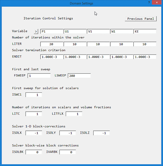
Image: ITERATION CONTROL
The POLIS Encyclopaedia entries on the individual items explain their function.
The default linear equation solver is based on Stone's Strongly Implicit method. To use the Conjugate - Residuals - Gradient solver for any variable, set ENDIT for that variable to GRND1. Circumstances under which this may be advantageous include:
Under these circumstances, it is now recommended to switch the 'Solver type' for P1 and TEM1 to AMG on the Main Menu - Models - Solution control panel, as this sovler is more effective and operates in parallel. It uses the same solver control variables as the default solver.
Numerics - Limits on Variables
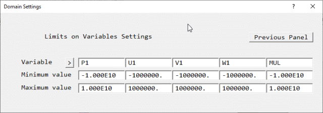
Image: LIMITS ON VARIABLES
This panel allows minimum and maximum values for all SOLVEd and STOREd variables to be set. The POLIS Encyclopaedia entries on the individual items (VARMIN, VARMAX) explain their function.
Numerics - Differencing Schemes
By default, the selected differencing scheme applies to all SOLVEd variables. The default scheme is the HYBRID scheme.
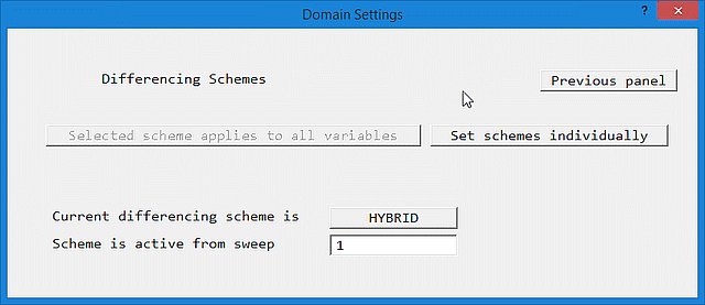
Image: DIFFERENCING SCHEMES 1
Clicking on 'Set schemes individually' allows the selection of different schemes for different variables.
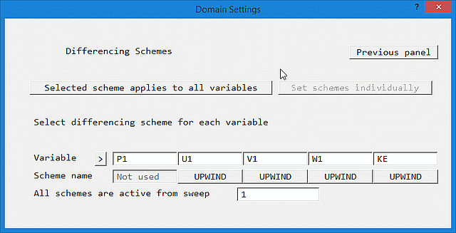
Image: DIFFERENCING SCHEMES 2
The complete list of scheme names is:
LUS          FROMM          CUS         QUICK          CDS
SMART        KOREN          VANL1       HQUICK         OSPRE
VANL2        VANALB         MINMOD      SUPBEE         UMIST
HCUS         CHARM
These are described in the POLIS Encyclopaedia entry SCHEMES FOR CONVECTION DISCRETIZATION.
This panel sets special variables for use in GROUND. The switch for PLANT is also on this panel.
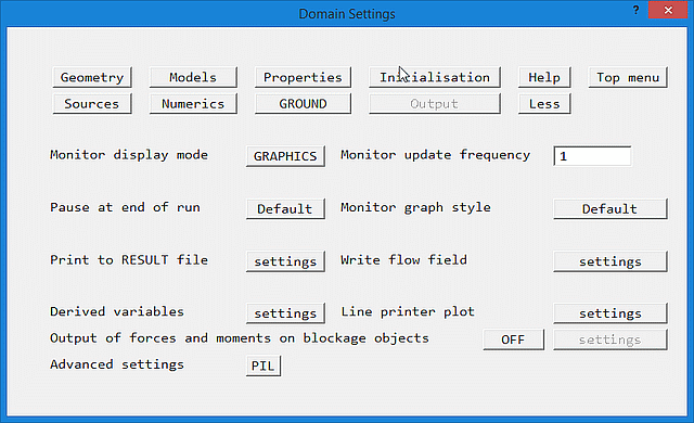
Image: OUTPUT
This panel gives options to:
This has three settings:
The solver can display convergence-monitoring information on the screen as graphs of:
Note that these options only apply to the 'classic' convergence monitor. The new convergence monitor introduced in 2022 can select any or all plots to display.
Output - Print to RESULT file settings
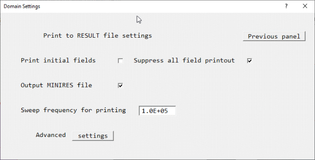
Image: PRINT TO RESULT
This panel controls whether the initial fields are to be printed, and whether to suppress the printout of the flow fields.
If 'Suppress all field printout' is ticked, the field printouts will be suppressed but the OUTPUT flags will not be changed, so that settings are not lost should the suppression be removed. In the Q1 this appears as
SPEDAT(SET,OUTPUT,NOFIELD,L,T)
in Group 19. The main reason for suppressing the printout is to reduce the size of the RESULT file for huge cases.
If 'Output MINIRES file' is un-ticked, the Earth solver will not produce the condensed convergence report file minires.htm at the end of the run. In the Q1 this appears as
SPEDAT(SET,GXMONI,MINIRES,L,F)
in Group 19.
Finer control over the printout is available on the Advanced settings panel:
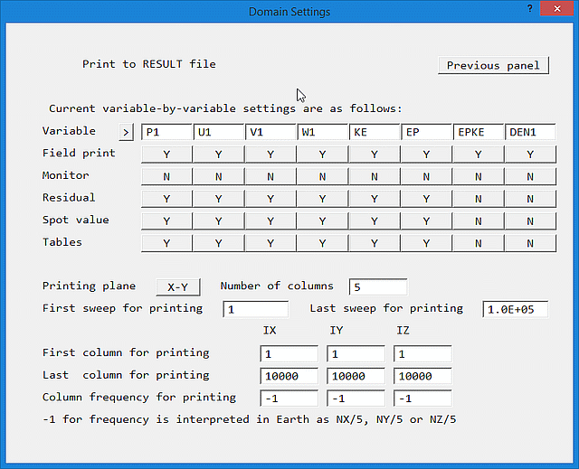
Image: DETAILED PRINT TO RESULT
The settings are equivalent to arguments 1,2,4,5 & 6 of OUTPUT:
The POLIS Encyclopaedia entries on the individual items explain their function.
Output - Write flow field settings
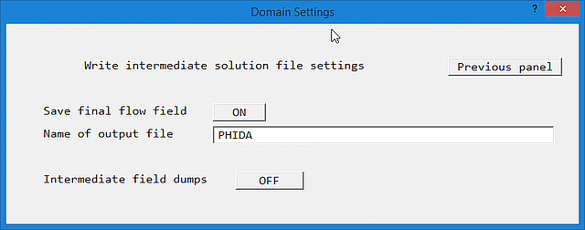
Image: INTERMEDIATE DUMPS - OFF
Once Intermediate field dumps are switched ON, this controls the sweep (for steady-state) or time-step (for transient) frequency with which flow fields are written to disk file.
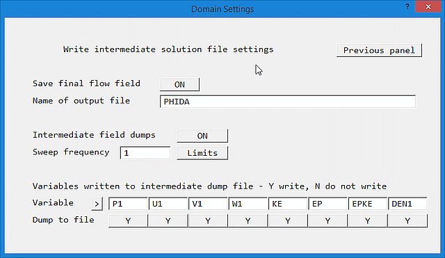
Image: INTERMEDIATE DUMPS - ON
The setting for 'Dump to file' for each variable determines whether that variable is written to the saved file or not. This can potentially save a lot of disk space by only writing the variables of real interest, but would also prevent such a 'thinned-out' file from being used as an Earth restart file.
In steady cases, the start letter for the dumped intermediate files is set to S.
In transient cases, intermediate flow fields can be dumped at regular time-step intervals. The names of these files are generated from a user-supplied letter, and the step number - e.g. A100. If the base name ends in 'IN', e.g. AIN, then the initial conditions are written to A0, and the Viewer will start the transient display at time t=0.
Note that if the start letter(s) are set to SW for a transient case, files will be dumped for the requested sweeps of the current step, not the final fields at the end of the time steps. Thus S1, S2, S3 etc will be the solutions of sweep 1, sweep 2, sweep 3 of the current time step, and will be overwritten on the next time step. This is intended as a debugging device to aid the investigation of poor convergence at a particular step.
The letter Q cannot be used as a base for saved intermediate files as there will be a danger of overwriting the Q1 input file!
If the case is one- or two-dimensional in X and Y (i.e. NZ=1), leaving the start-letter blank causes Earth to write out a special file called PARPHI, in which the Z direction is used for time. Each Z plane is the solution for that time step.
If PARSOL is active, a cut-cell data file will be produced at the same time as the intermediate flow field file. The names of these files are generated as PBC<letter><number> - e.g. PBCA100.
Although the names of output and intermediate files may be displayed as upper-case, the Earth solver will convert them to lower-case.
By default, field dumping starts at the first sweep or step, and continues throughout the run. The Limits button leads to a screen on which the first and last sweep or step for dumping can be set. It is very rarely necessary to set such limits, and users are advised not to do so unless specifically required.
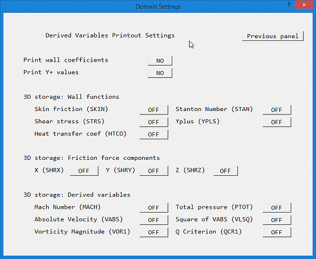
Image: DERIVED VARIABLE panel
Placing the Skin friction coefficient, Stanton Number, Shear stress (actually friction velocity squared, equivalent to shear stress divided by density), Yplus (non-dimensional distance to the wall) and heat transfer coefficient (in W/m2/K) into 3-D storage allows them to be plotted in the Viewer or PHOTON, as well as appearing in the RESULT file.
Note that the heat-transfer coefficients are only calculated for turbulent flow. To make them appear for laminar cases, the turbulent viscosity should be set to a very small value - say 1.0E-10.
The friction force components SHRX, SHRY and SHRZ are used in the force-integration routines to add the friction force to the pressure force acting on each object. If they are not stored, the integrated force will only contain the pressure component. Storage for the friction forces can also be activated from the Forces and moments ' Settings' panel.
If the Mach Number is stored, the Total or Stagnation Pressure (PTOT) is calculated from:
Ptot = (P1+PRESS0)*(1+((γ-1)/2)*M)γ/(γ-1)
If the Reference Pressure PRESS0 (Main Menu - Properties) is set to zero, the total pressure may go below zero, leading to an error-stop.
If the Mach Number is not stored, the total pressure is calculated from:
Ptot = (P1+PRESS0) + 0.5*ρ*Vabs2
When this is 'On', the Earth solver will integrate the pressure forces over all objects and print the force information to the RESULT file. Control over which objects are included in these calculations is provided on the 'Settings' panel. If the friction force components (SHRX, SHRY and SHRZ) have been placed in 3D store, the force integration will include them.
The moments of the X-, Y- and Z-direction forces about the X, Y and Z axes are calculated, and the point of action of the force is deduced.
The force and moment calculations are only valid for Cartesian and cylindrical-polar grids. The forces and moments are always printed in the Cartesian co-ordinate system. Positive moments are clockwise in a right-handed co-ordinate system.
For each face-cell (cell containing some surface area) of each blockage object, the force is calculated as:
fpi = P1*Ai : the pressure force, where Ai is the surface area normal to direction i (X,Y or Z)
ffi = SHRj*Aj +SHRk*Ak : the friction force, where Aj, Ak are the areas parallel to direction i
fti = fpi + ffi : the total force in each cell.
The forces are then summed over all the face-cells of an object to give the total force on the object:
Fti = sum(fti)
The moments about the X,Y and Z axes are then calculated as:
mx = fty.Z - ftz.Y
my = -ftx.Z + ftz.X
mz = ftx.Y - fty.X
where X,Y and Z are the distances of the cell face centre from the X,Y and Z axes. The moments are summed over all face-cells of an object to give the total moment about each axis:
Mi = sum(mi)
The moments of the individual forces about each axis are also summed:
Mzx = sum(ftx.Y); Myx = sum(-ftx.Z)
Mzy = sum(-fty.X); Mxy = sum(fty.Z)
Mxz = sum(-ftz.Y); Myz = sum(ftz.X)
The point of action of the integrated force (the position where the moment is zero) can now be deduced from expressions like:
Xm = Myz/Ftz; Ym = Mzx/Ftx; Zm = Mxy/Fty
Similar summations are performed over all objects to give the total force acting, the total moment, and the point of action of the total force.
Further control over what is printed is provided on the 'Settings' panel.
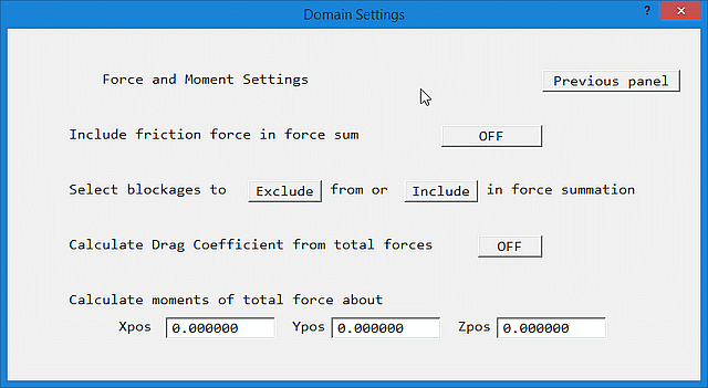
Image: FORCES SETTINGS panel
The settings are:
Image: FORCES SETTINGS panel with Drag CoefficientThe drag coefficients are then printed as:
Cdi = Fi/(0.5*RHOref*Velref*Arearef,i)
The Power is also printed as:
P = Ft*Velref
where Ft is the total force.
Mx' = Fy.(Zm-Zu)-Fz.(Ym-Yu)
My' = -Fx.(Zm-Zu)+Fz.(Xm-Xu)
Mz' = Fx.(Ym-Yu)-Fy.(Xm-Xu)
This displays the section of TR/326 relevant to the current panel. If the POLIS files cannot be found on the local computer, you are offered the opportunity to open the file from the CHAM website. Note that the location of the POLIS files is set in the CHAM.INI file as described here
This returns to the main graphics window, and applies all the changes made in the main menu. This button only exists on the Top menu.