The two figures below show the buttons on the VR-Editor hand-set, and label them with their functions. The functions are described in more detail in the subsequent sections.
If the handset is placed in the default location – at the upper-right of the main display window – it will retain that relative position when the size of the main window is changed. If it is moved away to some other location, it will stay there when the main window size is changed. Moving it back to the default position will make it ‘stick’ again.
The hand-set is divided into two separate parts - the movement controls and the domain and object controls.
Zoom in / Move Forward, Zoom Out / Move Backward, Reset View Parameters, View Left / Move Left, View Right / Move Right, View Up / Move Up, View Down / Move Down, Tilt Left / Angle Up, Tilt Right / Angle Down, Mouse control, Quick-Zoom
In addition to the View Control buttons located in the movement control part of the of the hand-set, it is possible to enter a 'fly-through' mode. In this mode, the geometry can be inspected in detail by moving inside the domain. This mode is shared with the VR-Viewer.
Axis Toggle, Rotate Object Down / Up, Top View Toggle, Mesh Toggle, Geometry Cells, Wire-Frame Toggle, Main Menu, Object Management, Duplicate Object or Group, Duplicate using Array, Delete object, X / Y / Z Position Up / Down, X / Y / Z Size Up / Down
The descriptions here apply equally to the icons on the handset or the icons on the toolbars. They behave in the same way.
A left-click switches the display of the Cartesian axes on and off.
A right-click brings up a dialog box from which the display of the axes including colour and line width, probe, probe cell position and title can be controlled individually.
Setting the 'Show cell position' tick-box will make the VR-Editor (and VR-Viewer) display the IX, IY, IZ position of the probe in the bottom-right corner of the main graphics window. In a Fine-Grid Volume case, it will display the cell numbers from the deepest visible fine-grid volume at the probe location.
When the 'Move' button is pressed, the selected item can be dragged to a new position with the mouse left button down. The 'Reset' button moves the item back to its default location. If the axes are moved away from their default location at the domain origin, they will stay fixed in that place until they are moved again, or the 'Reset' button is pressed.
The probe is a selectable item. Double-clicking on the probe displays the Probe Location Dialog.
This can be used to reset the probe location. The probe can be moved to a physical location, or to a cell centre. When moving to a physical location, the distance moved for each click on the up/down arrows is set on the Parameters tab under Increment. When moving to a cell location, the probe will always be placed at the cell centre.
In the VR-Viewer, the dialog will show the value of the currently selected variable at the probe location. There will also be two additional pages on the dialog which will show the location and value of the High and Low Spots for the current variable.
Set view centre will set the view centre of the image to the current probe location, thus centering the image on the probe.
The 'Parameters' tab is described under ' Settings - Editor Parameters' .
This toggles the display of a small window showing a top view of the geometry. It can help in orientation, especially when the mouse control is active. A left mouse click in the top-view window zooms it in one step, a right click zooms it out one step.
The bar across the Top View window (for the default magnification) represents the width of the main image, and the marker represents the axis about which image rotations take place.

Turning the mesh toggle ON causes the current grid to be displayed on the graphics image:
The orange lines are region boundaries. These are automatically created to match the edges of the object bounding boxes (see VR-Editor Object Dialogs - Object creation, Object Positioning). They are also grid lines. As objects are introduced, removed and resized, the region lines will adapt to match the object layout. The blue lines are 'ordinary' grid lines. By default, these are distributed according to the auto-meshing rules.
The mesh is displayed on a plane at the probe location. By default the plane is normal to the co-ordinate axis nearest the view direction. For example, if the view direction is along, or close to, +/-Z, the X-Y plane will be displayed, as in the image above. As the probe position and/or view directions are changed, the mesh display will also change to follow.
To manually select the displayed plane, click the pull-down arrow next to the mesh toggle
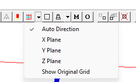
and choose the required plane. This plane will now be displayed regardless how the view direction is changed, until another direction or 'Auto' is chosen. The position of the plane is still controlled by the probe location.
The final option here 'Show Orginal Grid' applies to USP only allows the user to toggle between the USP refined grid and the original Cartesian grid.
The number of cells in any region, and the distribution within any region, can be set by clicking on the region to be modified. This is described in detail in Space and Time Grids.
When the mesh display is on, screen selection of objects is disabled. To select an object whilst the mesh is display is on, press the Ctrl key before clicking on an object on the screen, or select the object from the Object Management dialog list. Once an object has been selected, the regions created by that object are highlighted by thicker lines in purple, as shown below:
A left-click on the grid will bring up the Grid Mesh Settings dialog, from which the grid can be adjusted.
A right-click on the grid will bring up the interactive meshing tool.
PARSOL
The geometry cells button outlines the cells, lying on a plane at the probe position, which intersect any object. The plane is normal to the co-ordinate axis nearest the view direction. For example, if the view direction is along, or close to, +Z, the X-Y plane will be displayed.
SPARSOL
The geometry cells button displays how the objects intersect the grid lines, either along cell centres or cell corners. The plane is normal to the co-ordinate axis nearest the view direction. For example, if the view direction is along, or close to, +Z, the X-Y plane will be displayed.
This display can be very helpful in checking how well the geometry is being detected by the grid.
A right-click on the geometry cells toggle brings up a dialog which gives more detailed control over how the grid lines are displayed.
If the 'Gridline colour index' is set to -1, then only grid lines within objects will be drawn.
This cycles through all available object rotations. See Object Orientation for a description.
The bounding-box toggle switches the graphics display between a shaded, hidden line picture, and a wire-frame representation, as shown below:
Image: HIDDEN LINE
PICTURE
Image: WIRE FRAME
REPRESENTATION
The wire-frame view can make it easier to see details inside hollow objects.
If no object is selected, this toggle acts as a master switch for all objects. If an object has been selected, it acts for that object.
Wire-frame mode can be activated for individual objects from the right-click context menu, the Action menu of the Object Management dialog or the Options tab of the Object dialog.
This leads to the Top panel of the Main menu. The Main menu is used to make all the domain-related settings. The main menu panels are described in VR-Editor Main Menu.
The Main Menu can also be reached from Settings - Domain attributes on the Top Menu bar.
This leads to the Object Management dialog box. This is fully described in VR-Editor Object Management.
If the current selection is a single object, then it and all its attributes - type, geometry, rotation etc. will be duplicated at the same position as the original. If a group of objects is selected, the entire group will be duplicated. See VR-Editor Object Management - Object Menu for a more detailed description.
The selected object, or group of objects, can be duplicated a given number of times in each co-ordinate direction with a given spacing. See VR-Editor Object Management - Object Menu for a more detailed description.
This will delete the currently-selected object or group. If no object or group is selected, the Object Management dialog box listing all the objects is shown. The objects can now be selected for deletion by highlighting from the list. The deletion list can be confirmed or modified before the deletion takes place.
Note that objects cannot be undeleted!
See VR-Editor Object Management - Action Menu for a more detailed description.
These buttons move the origin of the bounding box of the currently selected object in the three co-ordinate directions. See VR-Editor Object Dialogs - Object 'Place' Page for more details.
It is possible to double-click on the data-entry boxes next to the up/down button, and type in exact values. This is equivalent to double-clicking on an object, and entering the positions in the Object Dialog Box Place panel.
In a Cartesian system, the position can denote the location of the low-X,low-Y,low-Z corner of the object, or the location of the mid-point of the bounding box. The choice is made on the VR-Editor Object Dialogs - Object 'Place' Page.
In a cylindrical-polar system, there are more choices.
In a Body-Fitted (BFC) system, the object positions are specified in terms of cell corners in the I,J and K directions. The origin of the grid is at (I,J,K) = (0,0,0).
If more than one object is selected, these buttons move the first object to be selected. All the other selected objects are moved by the same amount, thus keeping the relative positions constant.
If one or more of the selected objects are 'constrained by the domain', movement will stop when any object touches the domain boundary. If they are all 'not constrained', they can be moved at will through the domain boundaries.
If no object is selected, these buttons move the probe. To see which cell the probe is
in, right click on the Axis Toggle / View Options button ![]() and turn 'Show Cell Position' on. The probe cell
location will be displayed in the bottom-right corner of the graphics screen.
Alternatively, double-click on the probe to bring up a dialog from which
the probe position can be changed.
and turn 'Show Cell Position' on. The probe cell
location will be displayed in the bottom-right corner of the graphics screen.
Alternatively, double-click on the probe to bring up a dialog from which
the probe position can be changed.
These buttons change the size of the rectangular bounding box of the currently selected object. See VR-Editor Object Dialogs - Object 'Size' Page for more details.
It is possible to double-click on the data-entry boxes next to the up/down button, and type in exact values. This is equivalent to double-clicking on an object, and entering the sizes in the Object Dialog Box Size panel. Note that the display is not updated until after either a click into the next input box, or into the graphics image.
In a cylindrical-polar system, the X and Y direction sizes are set as follows:
Geometry name |
X Size | Y Size |
| Any geometry with file name starting 'POL' (all the default geometries) | dq radians | dr metres |
| All others | dx metres | dy metres |
The effect of this is that default geometries, such as POLCUB.DAT, will bend to follow the grid, whereas non-default geometries, such as WEDGE1.DAT or any CAD geometry will retain their correct shape.
IMAGE: Default and non-default geometries in a polar grid
For further information see ' VR-Object Dialog - Object 'Size' Page'.
In a Body-Fitted (BFC) system, the object sizes are specified in terms of cell numbers in the I,J and K directions.
If no object is selected, these buttons will change the size of the domain. The size of a BFC domain cannot be changed from here.
The left mouse button operates Zoom In; the right mouse button operates Move Forward. Zoom In is equivalent to increasing the zoom factor in a camcorder. Move Forward is equivalent to moving the camera nearer the subject, whilst retaining the same zoom factor.
The left mouse button operates Zoom Out; the right mouse button operates Move Backward. Zoom Out is equivalent to decreasing the zoom factor in a camcorder. Move Backward is equivalent to moving the camera further away from the subject, whilst retaining the same zoom factor.
The left mouse button operates View Left, and the right mouse button operates Move Left. View left is equivalent to rotating the image clockwise about a vertical axis, whilst Move Left is equivalent to moving the viewpoint horizontally to the left (i.e. the image appears to move to the right!)
The left mouse button operates View Right, and the right mouse button operates Move Right. View Right is equivalent to rotating the image anti-clockwise about a vertical axis, whilst Move Right is equivalent to moving the viewpoint horizontally to the right (i.e. the image appears to move to the left!)
The left mouse button operates View Up, and the right mouse button operates Move Up. View Up is equivalent to tilting the image away from the observer about a horizontal axis, whilst Move Up is equivalent to moving the viewpoint vertically up (i.e. the image appears to move down!)
The left mouse button operates View Down, and the right mouse button operates Move Down. View Down is equivalent to tilting the image toward the observer about a horizontal axis, whilst Move Down is equivalent to moving the viewpoint vertically down (i.e. the image appears to move up!)
The left mouse button operates Tilt Left, and the right mouse button operates Angle Up. Tilt Left is equivalent to rotating the image anti-clockwise about an axis normal to the screen, whilst Angle Up increases the perspective - equivalent to decreasing the focal length of a camera.
The left mouse button operates Tilt Right, and the right mouse button operates Angle Down. Tilt Right is equivalent to rotating the image clockwise about an axis normal to the screen, whilst Angle Down decreases the perspective - equivalent to increasing the focal length of a camera.
For two-dimensional cases, it can be helpful to use Angle Down to completely remove any perspective.
This button leads to the Reset View Parameters dialog:
On this dialog:
If the image has been lost by zooming or rotating, a click on Reset View Parameters followed by Fit to Window will restore an understandable view.
On the toolbar, most of the dialog functions are also provided as a pull-down menu.
Once the Mouse Control button is pressed, or whenever the Movement control panel is closed, the mouse can be used to control the view in the VR-Editor or VR-Viewer. This is in addition to the movement control buttons which remain active at all times.
The following table lists the effects of various mouse movements, using the same terminology as above.
| Mouse button held down | Mouse movement | Effect | Equivalent key |
| Left | Left | View left | left-click on |
| Right | View right | left-click on |
|
| Up | View up | left-click on |
|
| Down | View down | left-click on |
|
| Right | Left | Tilt right | left-click on |
| Right | Tilt left | left-click on |
|
| Up | Zoom out | left-click on |
|
| Down | Zoom in | left-click on |
|
| Middle (or both) | Left | Move left | right-click on |
| Right | Move right | right-click on |
|
| Up | Move down | right-click on |
|
| Down | Move up | right-click on |
|
| Shift+Left | Left | Rotate image right about viewer | None |
| Right | Rotate image left about viewer | None | |
| Up | Rotate image down about viewer | None | |
| Down | Rotate image up about viewer | None | |
| Shift+right | Left | None | None |
| Right | None | None | |
| Up | Move back | right-click on |
|
| Down | Move forward | right-click on |
The Top View window can be very helpful in clarifying the effects of the various viewing controls.
To zoom into a region without panning and dragging, place the cursor where the centre of the zoomed image is to be. Press the control key <Ctrl>, and with it held down, hold the left mouse button down and move the cursor to the left or right. A box will follow the movement of the cursor. When the mouse button is released while the control key is down, the area within the box will be expanded to fill the screen.
Image: ZOOM BOX
Image: ZOOMED VIEW
The last quick-zoom may be undone by using 'Ctrl+Z' or the 'Backspace' keys.
The VR-Editor and VR-Viewer share the same viewing controls on their hand-sets. In addition to these, both share a 'fly-through' mode.
This enables the observer to move inside the domain, and inspect the geometry and flow in detail.
To activate the 'fly-through ' mode, place the cursor on the Main graphics window (somewhere near the middle) and press the space bar on the keyboard. A white square will appear at the location of the cursor. As the cursor is moved away from the square in various directions, the view will change. The further the cursor is moved from the square, the faster the movement.
Note that the Mouse control button must be off for fly-through mode to be available.
| Direction relative to square | Mouse button held down | Effect |
| Up | none | Move forward |
| Down | none | Move back |
| Left | none | Turn left |
| Right | none | Turn right |
| Up | Left | View direction up |
| Down | Left | View Direction down |
| Left | Left | Tilt left |
| Right | Left | Tilt right |
| Up | Right | Move up |
| Down | Right | Move down |
| Left | Right | Move left |
| Right | Right | Move right |
The 'fly-through' mode is exited by pressing the space bar again.
If the view gets completely lost, clicking on the Reset View Parameters button followed by 'Fit to window' will restore an understandable view.