New Object, Import CAD Object, Import CAD Group, Import Object, Copy Object, Array Object, Select All, Refresh, Close
Open object dialog, Hide object, Reveal object, Delete object, Modify colour, Object Wireframe, Object affects grid, Object constrained by domain, Object selectable, Move to object centre, Datmaker operations, Shapemaker, Surface vectors, Surface vectors, Surface contours, Dump surface values, Dump object profile, Show nett sources
In the VR-Editor, all geometrical features are represented by objects. They may represent for example: blockages, inlets, outlets or heat sources. Complex objects can often be represented by suitable combinations of simpler objects.
Objects can be volumes or areas, but never lines. Even in a two-dimensional case, PHOENICS requires a depth in the third dimension, or in a one-dimensional case, width and depth. This is because of the finite-volume numerical solution method.
This chapter describes how objects can be manipulated - created, modified or deleted. The next chapter gives more detail on how to size and position objects, how to assign shapes to objects and how they interact with the mesh. VR Object Types and Attributes describes the attributes of each object type.
Objects are manipulated via the Object Management Panel (OMP), which is reached by:

The OMP contains a list of the object names along with associated key data for each object . By default the objects are sorted by their reference number, column two. They may also be sorted by name, type, geometry or colour by clicking on the appropriate column header. The colour number listed is the palette entry for the first facet in the geometry file.
Objects can be selected from the list using standard Windows techniques:
When the OMP is open, multiple objects can also be selected by picking them from the screen with the control key held down. If the shift key is held down as well, all objects under the cursor will be selected, not just the nearest one. (This only works with the Legacy renderer).
The final column in the OMP, labeled 'Selectable', determines whether an object can be picked from the screen with the cursor or not. Objects can always be selected from the OMP list.
The OMP has four pull-down menus which enable objects to be created, updated or deleted. The updating and deleting actions are performed on all the selected objects. Each column also has its own context menu, displayed by right-clicking in the column.
Object Menu, Action Menu, View Menu, Group Menu, Context Menu
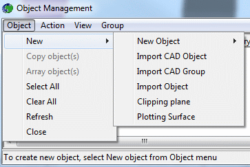
New Object, Import CAD Object, Import CAD Group, Import Object, Clipping plane, Plotting Surface, Copy Object, Array Object, Select All, Refresh, Close
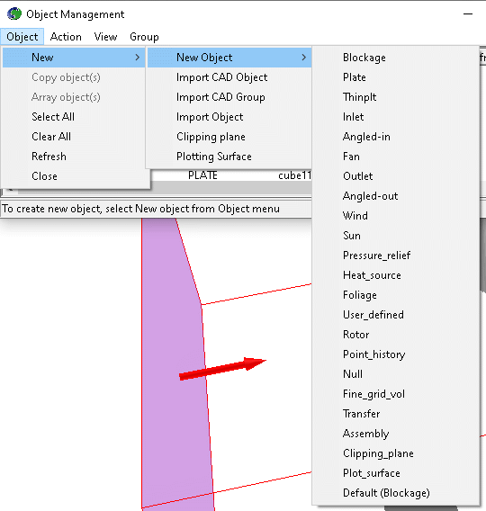
Creates a new object of the selected type at the origin and opens the Object Dialog for it. Further details on the use of the Object Dialog are contained in the next two chapters.
Creates a new object and opens the CAD Import dialog for it.
Opens the Group CAD import dialog, which allows a number of CAD files to be imported in one action. Each CAD file specified will create a new object of the same type and with the same attributes as the first. If there are many objects in the group, and they all have the same non-default attributes it will be easier to create a new object of the right type, set its attributes, and then perform a group import from the Shape tab of the object specification dialog.
Creates a sequence of objects from the contents of a POB file. The first object is always an ASSEMBLY object, which acts as a 'container' for the component objects. See VR Object Types and Attributes - Assembly for more details.
Creates a new Clipping_plane object.
Creates a new Plotting Surface object. This is used in the Viewer to display contours and vectors on an arbitrary surface.
Copy Object(s)
This makes a copy of the selected object(s), including all attributes. Objects and
active groups can also be duplicated by clicking on the Duplicate Object or Group button ![]() of the hand-set.
of the hand-set.
The duplicated object or group is always created with its origin at the same position as the original. It can then be moved to its desired location.
Array Object(s)
Arraying is a variation on duplication. It allows the creation of an entire array of objects or groups, all copied from the original.
Select one or more objects from the list, then click Object - Array objects.
Alternatively, click on an object to make it the current object and click on the Duplicate
using array button ![]() on the hand set. The dialog box shown below will appear:
on the hand set. The dialog box shown below will appear:
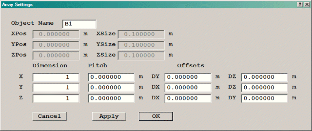
If one or more of the objects to be arrayed is 'constrained by the domain', and 'Dimension * Pitch' or 'Dimension * Offset' is too large to fit in the domain, a warning message is displayed, and the option to adjust the pitch or offset is offered. However, if the Dimension is 2, it is assumed that the user wanted to duplicate the object at the other end of the domain, and the pitch is automatically adjusted to fit.
If the object or objects to be arrayed are all 'unconstrained', no checks are made on the final positions of the created objects.
Selects all objects (except the domain) in the object management panel.
It is possible for the object management to become out of sync with the current status of the model, in these cases use refresh to update its contents.
Closes the object management panel.
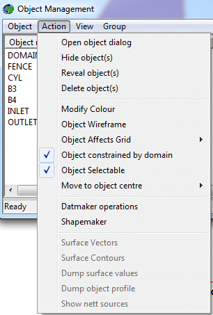
Open object dialog, Hide object, Reveal object, Delete object, Modify colour, Object Wireframe, Object affects grid, Object constrained by domain, Object selectable, Move to object centre, Datmaker operations, Shapemaker, Surface vectors, Surface contours, Dump surface values, Dump object profile, Show nett sources
This opens the object dialog box for the current object. The current object is the one highlighted in the list. If more than one object has been selected, the dialog box for the last object to be selected is opened. When the object dialog is closed, the changes made can be optionally propagated through all the other selected objects which are of the same type.
Care should be taken when propagating changes to ensure that unwanted changes are not made; for example propagating changes through a group of INLET objects where some are side High and some are side Low will result in all of them taking the side of the one whose dialog has been displayed.
Hide object(s)
This hides (makes invisible) all the currently selected objects.
This reveals (makes visible) all the currently selected objects.
This deletes all the currently selected objects. The user will be prompted for confirmation before objects are deleted. Objects cannot be undeleted!
Opens the object dialog for the current object on the options page; click on the object colour button to modify the colour. The object transparency may also be set from here. When the object dialog is closed the colour changes will be applied to all selected objects.
Check menu item toggles wireframe mode for selected objects.
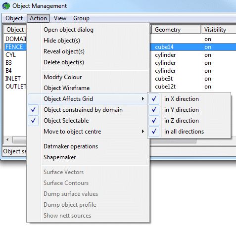
Check menu item toggles whether the selected objects affect the model grid in the X, Y or Z directions. Selecting 'All' turns all directions on or off together.
Check menu item toggles whether the selected objects are constrained by the domain.
When set to 'Yes', the object can be picked from the screen with the cursor. When set to 'No', it can only be selected from the OMP list. This can be very useful when objects get in the way of the target object.
Move to object centre.
This will redraw the screen image with the view centre set to the centre of the selected object's bounding box. This is useful for locating a particular object in a scene by focusing on it. If the Domain is selected, the view centre is moved to the centre of the domain.
This will move the probe to the centre of the selected object's bounding box.
This moves the probe to the centre of the selected object's bounding box and then redraws the screen image with the view centre set to the new probe position.
This brings up the Datmaker dialog, described here. Datmaker performs repair and boolean operations on objects.
Shapemaker is a utility which can create many different parameterised shapes, from a pre-defined list. If an object has been selected, its geometry will be replaced by that created during the Shapemaker session, as described here.
Surface vectors (Viewer only)
Check menu item toggles whether vectors are displayed on surface of current object. Surface vectors cannot be displayed at the same time as surface contours.
Surface contours (Viewer only)
Check menu item toggles whether surface contours are displayed on the current items. Surface contours cannot be displayed at the same time as surface vectors.
Dump surface values (Viewer only if Surface contour ticked)
Writes a file, <objname>_<varname>.csv, which contains four columns of data, x,y,z,value, which were used to generate the surface contours. So, if the current object was named FENCE and the current variable is Pressure, the filename would be FENCE_Pressure.csv.
Dump object profile (Viewer only if Surface contour ticked)
Writes a file similar to the above, although, it will only dump the values along the current slice. The filename is composed as <objname>_<varname>_<plane>_<planeval>.csv. Where <objname> is the object name, <varname> the current variable, <plane> the currently selected plane (X,Y or Z) and <planeval> the current position of that plane. This latter will be moved to the cell centre in the file. If the current object was named FENCE, the current variable was Pressure, the current plane was X at X=0.5, the file name would be FENCE_Pressure_X_0.5.csv.
Show nett sources (Viewer only)
Displays sources and sinks for the selected object in the text box. The values are read from the 'Sources and sinks' section of the RESULT file. Force and moment data for blockages is also displayed if present.
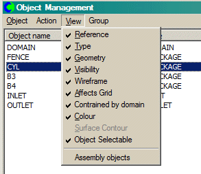
The first ten check menu entries indicate whether the corresponding column is visible in the listbox. Note that the surface contour column is only visible in the Viewer. The final check menu item 'Assembly objects' indicates whether the child assembly objects are visible in the list of objects.
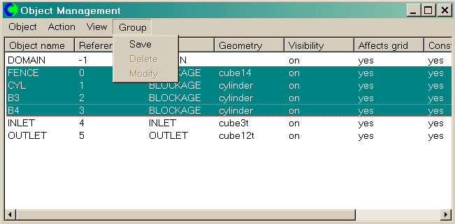
When more than one object is selected, a temporary group is created. This group may be saved to be recalled later by using this option. Any saved group will subsequently be listed in the list of objects in the object management panel. Details of any saved groups will be written to the Q1.
If the current object is a saved group then this option becomes active and may be used to delete the group. The user is also prompted as to whether they wish to also delete the objects contained in the group.
This option may be used to modify the membership of a saved group.
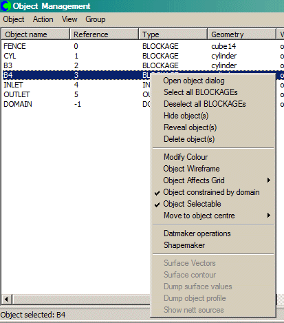
A context menu is available in the OMP by clicking the right mouse button on one of the columns. The context menu is an extension to the Action menu described above. The items in the menu depend on the column. It enables the rapid selection of objects of a single type or geometry, and also provides a shortcut access to the geometry generation program Shapemaker.
A similar context menu is accessed by right-clicking on an object in the graphics window.
The context menu for the 'Reference' column is different from the others - it allows the sequence number of the selected object(s) to be changed.
- Top makes the selected object the first in the entire list
- Page up moves the selected object to the top of the section of the list visible in the listbox
- Line up moves the selected object up one in the list
- Line down moves the selected object down one in the list
- Page down moves the selected object to the bottom of the section of the list visible in the listbox
- Bottom makes the selected object the last in the entire list