For the latter it allows formulae describing the motion to appear as 'position', 'size' and 'rotation-angle' arguments of the object-describing functions, BOX, SPHERE etc; and it attaches momentum sources describing the effect of the motion explicitly in the Q1 file.
The built-in MOFOR coding is then not activated.
MOVOB statements make use of the POS function for setting the X, Y and Z coordinates and the rotation angles about the X, Y and Z axes of a moving object as functions of the time variable, TIM:
In case 360, the relevant statements are:
char(vel,gravt,times)
vel=10.; gravt=9.81; times=tim
(MOVOB of SPHERE1 is POS(:times:*:vel:,:times:*:vel:-0.5*:gravt:*:t$
imes:^2,0,0,0,0))
(MOVOB of SPHERE2 is POS(-:times:*:vel:,0,0,0,0,0))
These dictate a motion which, after the first time step appears thus:
Its distance of vertical travel will be about the same, because the acceleration term has not had time to become significant.
The presence of one sphere near the bottom left-hand corner in the just-seen picture suggests that this indeed sphere 1.
> OBJ,    NAME,        SPHERE1
> OBJ,    POSITION,    0.000000E+00, 0.000000E+00, 0.000000E+00
> OBJ,    NAME,        SPHERE2
> OBJ,    POSITION,    2.100000E+01, 3.000000E+00, 0.000000E+00
in which the 'position' lines show that sphere1 starts at the origin of the coordinate system, whereas sphere2 starts at x=21 and y=3.
This provides two pieces of information, namely:
However, the moffile approach is rather too clumsy for motions which are simple enough to be described by formulae. This is indeed the reason for the introduction of the In-Form MOVOB keyword.
As will now be seen, the 'hierarchy' and 'offset' concepts are also embodied in MOVOB.
It is exemplified in library cases 381 and 382.
In-Form can calculate coordinates of a moving body position by the formula specified in "(MOVOB" In-Form statements which uses POS and OFFSET special functions. "(MOVOB" statement has next format:
(MOVOB of VR_OBJ_NAME is special_FUNCTION() with PARENT=PARENT_NAME)where VR_OBJ_NAME is the name of the VR object name which is connected to a appropriate object-related coordinate system for which the current attributes are set.
The special In-Form flag "!PARENT=PARENT_NAME" set the name of parent object-related coordinate systems. The OFFSET function describes the hierarchy part of the attribute settings. OFFSET is In-Form special function of declaring the frames of reference of object-related coordinate systems. Each new OFFSET function declares a new frame coordinate system and describes its position relative to its
parent system.
OFFSET has the following format:
OFFSET(arg1,arg2,arg3)
where arg1 ,arg2 and arg3 are formulas f defining the of the new coordinate origin relative to those of its parent.
Each formula can contain the TIM variable which is current time in seconds at the current time step.
The task is to describe the linear motion of a 2D rectangular object called "BLOCK" with uniform velocity of 3m/s in Z-direction of computational domain starting from a given initial, stationary position of the object.
The movement is along Z-axis. The initial position and the sizes of the BLOCK are specified in the Q1 file. Z coordinates of moving BLOCK object are described as
Z velocity component[m/s] * current time[s].The following picture displays the result. It is input-library case v119
.
The description the hierarchy part is not mandatory as there is only one moving object. Therefore it is enough to define the Z position of moving object in each time step, thus:
(MOVOB of BLOCK is POS(0, 0, 3*TIM, 0, 0, 0))
More-complex movement: translation and rotation. The following image reveals what is to be simulated. It is input-library case v120
.

The case exemplifies the specification of the attributes for composite movement: the translation of a rotating block. It results in the effect of the rolling 2D rectangular object with the longitudinal (X-direction) velocity component of 0.5 m/s and the angular rotation about block centre line (Z-axis) of 30 degrees per seconds. The movement starts from the initially steady position defined in the Q1 file.
The hierarchy part is described as follows:
 (MOVOB of CHAM is OFFSET(0&0&0))
 (MOVOB of BLOCK is OFFSET(0.55&0.9&0) with PARENT=CHAM)
The OFFSET defines the position of the rotation axis relative to the root frame: it places the Z-axis in the middle of BLOCK initial position.
The movement is along X-axis and the rotation about Z-axis. X coordinates of moving BLOCK object and rotation angles are described as
(MOVOB of BLOCK is POS(0.5*tim&0&0&0&0&-30*tim))
Independent motions: crossing paths
The case exemplifies the setting-up the attributes for the independent movements of two objects following their own linear trajectories in 2D, X-Y, computational space.
The movement of the first object, called SPHERE1, starts from its stationary position at the west-south corner and follows a prescribed parabolic trajectory. The velocity of SPHERE1 is 10 m/s and is defined by interaction of gravitation force.
The second object, SPHERE2, starts at east-south corner of the domain and follows the linear trajectory crossing the one from right to left. It has the constant velocity component of -10 m/s in X-direction and 3 m/s in Y-direction.
The movement starts from the initially steady position defined in the Q1 file.
The description the hierarchy part is not mandatory as two moving objects move inside one root coordinates system. Therefore it is enough only to define the position of moving objects in each time step.
The movement of SPHERE1 object is along diagonal of XY plane. X and Y coordinates of moving object are described as
 vel=10.; gravt=9.81
 (MOVOB of SPHERE1 is POS(tim*:vel:&tim*:vel:-0.5*:gravt:*tim^2&0&0&0&0))
The movement of SPHERE2 object is along X-axis from right to left. X coordinates of moving object are described as
(MOVOB of SPHERE2 is POS(-tim*:vel:&0&0&0&0&0))
Connected objects: falling of a cracked wall
The case exemplifies the setting-up the attributes for the connected movements of two objects following their relative rotation in 2D, Y-Z, computational space.
The movement of the first object, called BLOCK, starts from its stationary position as a vertical wall with its base placed next to the middle of the bottom domain boundary. BLOCK is allowed to fall. It does so by rotating clockwise about X-axis of its south-high corner. The angular velocity of the fall is ,5 degrees per second.
Initially, the second smaller object, TIP, sits stationary on the top of BLOCK and can be regarded as a part of the wall. Once the whole wall starts to fall, it cracks and TIP begins to move in opposite direction by rotating counterclockwise about X- axis of the north-low corner of the BLOCK. The angular velocity of the TIP relative to the BLOCK is 180 degree per second.
The hierarchy part is described as follows:
 (MOVOB of BLOCK is OFFSET(0&0&2.1))

 (MOVOB of TIP is OFFSET(0&2.5&-0.5) with PARENT=BLOCK)
Two frames are defined: BLOCK is a parent joint, and TIP is the BLOCK's child.
The OFFSET of BLOCK defines the position of the rotation axis relative to the root frame: it places the origin of parent related coordinate frame at the south-high corner of BLOCK initial position.
The OFFSET of TIP defines the position of the rotation axis relative to the BLOCK frame: it places the origin of its coordinate frame at the north-low corner of BLOCK initial position.
The movement of BLOCK object is a rotation clockwise about X plane. Rotation angle is described as
(MOVOB of BLOCK is POS(0&0&0&75*tim&0&0))
The movement of SPHERE2 object is a rotation counterclockwise about X plane. X coordinates of moving object are described as
(MOVOB of TIP is POS(0&0&0&-180*tim&0&0))
Agitated reactor
Impellers are the units one most commonly associates with stirred reactors. The particular design considered here consists of the ROD, mounted on rotating vertical SHAFT. The rod carries two PADDLEs, which agitate the flow. As the impeller rotates it forces the surrounding fluid to rotate with it. The design with rotating paddles is used when "in-depth" mixing is a must.
The task of the exercise is to provide the attributes for connected movements of SHAFT-ROD-PADDLEs assembly following their relative rotation in 3D computational space. The angular velocity of the shaft is 60rpm.
The hierarchy part is described as follows:
 (MOVOB of CHAM is OFFSET(0&0&0))

 (MOVOB of SHAFT is OFFSET(0.15&0.25&0.25) with PARENT=CHAM)

 (MOVOB of ROD is OFFSET(0&0&0) with PARENT=SHAFT)

 (MOVOB of PADDLE1 is OFFSET(0&0&0) with PARENT=ROD)

 (MOVOB of PADDLE2 is OFFSET(0&0&0) with PARENT=PADDLE1)
Four frames are defined: SHAFT is a parent joint, and ROD, PADDLE1 and PADDLE2 are the SHAFT's children.
The OFFSET of SHAFT defines the position of the rotation axis relative to the ROOT frame: it places the origin of parent related coordinate frame at the middle of the SHAFT bottom face of its initial position.
The ROD and PADDLEs rotate about the same axis and has no freedom to move relatively to SHAFT. The OFFSETs of ROD and both PADDLEs are zero.
The movement of SHAFT object is a rotation clockwise about X plane. Rotation angle is described as
(MOVOB of SHAFT is POS(0&0&0&360*tim&0&0))
However, even before the existence of MOVOB, In-Form had a means of causing its own 'In-Form objects' to move, and to move the fluid with them. How this works will now be illustrated.
The fluid motion is achieved by attaching momentum sources to the In-Form objects. This was not in evidence when the MOVOB keyword was being used; but such sources were being introduced, nevertheless, behind the scenes.
Studying the 'source' statements associated with moving In-Form objects therefore throws some indirect light on how MOFOR works.
So the 765 library case sets the linear motion of two hot spherical bodies to follow a horizontal path as
char(xce,yce,zce,radius; xce=.5+.5*(tim/100.-1); yce=0.1 + 01*(tim/100.-1); zce=.05; radius= .25
(INFOB at FIRST is SPHERE(:xce:,:yce:,:zce:,:radius:) with INFOB_1)
xce=.5+.25*(tim/100.-1); yce=1.5; zce=.05; radius= .25
(INFOB at SECOND is SPHERE(:xce:,:yce:,:zce:,:radius:) with INFOB_2)
It should be noted that the '(INFOB' statement can contain several long formulae.
These can be
spread over several lines in the Q1 file, with a '$' symbol as the last character of a line acting as a continuation
marker.
When the Q1 file is rewritten at the end of an interactive section, lines longer than 68 characters will
be automatically folded with a $ at column 68.
In the setting of long formulae it is recommended to use intermediate
symbolical variables, as shown above.
The maximum possible length of a formula in any In-Form statement is 1000 symbols.
Heat sources within In-Form objects are represented thus:
(SOURCE of TEM1 at FIRST is 100. with INFOB_1)
(SOURCE of TEM1 at SECOND is 100. with INFOB_2)
The 770 library case set steady rotated In-Form object for simulation two paddle-stirred reactor. The rotated paddle is describes by In-Form:
REAL(ANGVL); ANGVL=4.*PI/1. ! Number of revolutions, 1/s.
REAL(X0,Y0); X0=0.5; Y0=0.5 ! X and Y coordinate of centre of impeller
char(ang,dx1,dx2,dy1,dy2); ang=:ANGVL:*TIM; dx1=:hsid2:*SIN(:ang:); dx2=:hsid1:*COS(:ang:) dy1=:hsid2:*COS(:ang:); dy2=:hsid1:*SIN(:ang:)
(INFOB at PATCH1 is BOX(:x0:-:dx1:-:dx2:,:y0:-:dy1:+:dy2:,0,0.1,0.7,10,0,0,:ang:) with INFOB_1)
The cartesian components of paddle velocity are set
(SOURCE of U1 at PATCH1 is :ANGVL:*(YG-:Y0:) with INFOB_1!FIXV)
(SOURCE of V1 at PATCH1 is :ANGVL:*(:X0:-XG) with INFOB_1!FIXV)
The inclined linear motion of rectangular object is submitted in 784 library case. Here four immobile In-Form objects (1, 2, 3 and 4) describe the geometry of blading sections of the chamber.
(INFOB at WHOLE is BOX(0.,.07,0.,.04,.03,1.,0.,0.,0.) with INFOB_1)
(INFOB at WHOLE is BOX(.07,0.,0.,.03,.04,1.,0.,0.,0.) with INFOB_2)
(INFOB at WHOLE is BOX(.04,.07,0.,.05,.03,1.,0.,0.,:-PI/4:) with INFOB_3)
(INFOB at WHOLE is BOX(.07,.04,0.,.03,.05,1.,0.,0.,:PI/4:) with INFOB_4)
Each of them is a solid body with appropriate installations inside objects
(STORED of VPOR at WHOLE is 0. with INFOB_1)
(SOURCE of U1 at WHOLE is 0. with INFOB_1!FIXV)
(SOURCE of V1 at WHOLE is 0. with INFOB_1!FIXV)
(STORED of VPOR at WHOLE is 0 with INFOB_2)
(SOURCE of U1 at WHOLE is 0. with INFOB_2!FIXV)
(SOURCE of V1 at WHOLE is 0. with INFOB_2!FIXV)
(STORED of VPOR at WHOLE is 0. with INFOB_3)
(SOURCE of U1 at WHOLE is 0. with INFOB_3!FIXV)
(SOURCE of V1 at WHOLE is 0. with INFOB_3!FIXV)
(STORED of VPOR at WHOLE is 0. with INFOB_4)
(SOURCE of U1 at WHOLE is 0. with INFOB_4!FIXV)
(SOURCE of V1 at WHOLE is 0. with INFOB_4!FIXV)
Two next In-Form objects (5 and 6) describe the geometry of a valve and a valve holder.
Description of a geometry of a valve
X and Y coordinates of a valve in the first time step
REAL(XVAL,YVAL); XVAL=0.065; YVAL=0.035
Moving of a valve during one time step
REAL(DMOV); DMOV=THROW/LSTEP; DMOV=DMOV/1.414
INTEGER(HLS,HLS1,HLS2); HLS=LSTEP/2; HLS1=HLS+1; HLS2=HLS+2
CHAR(CXP,CYP); CXP=:XVAL:-:DMOV:*(:HLS:-ABS(ISTEP-:HLS1:)); CYP=:YVAL:-:DMOV:*(:HLS:-ABS(ISTEP-:HLS1:))
(INFOB at WHOLE is BOX(:CXP:,:CYP:,0.,.01,.042,1.,0.,0.,:-PI/4:) with INFOB_5)
Description of a geometry of the valve holder
X and Y coordinates of the valve holder in the first time step
REAL(DXH,DYH); DXH=0.0113; DYH=0.0252
(INFOB at WHOLE is BOX(:CXP:-:DXH:,:CYP:+:DYH:,0.,.01,.11,1.,0.,0.,:PI/4:) with INFOB_6)
Fixation of the valve velocities into valve
(SOURCE of U1 at WHOLE is :UP: with INFOB_5!FIXV)
(SOURCE of V1 at WHOLE is :VP: with INFOB_5!FIXV)
Fixation of the valve velocities into valve holder
(SOURCE of U1 at WHOLE is :UP: with INFOB_6!FIXV)
(SOURCE of V1 at WHOLE is :VP: with INFOB_6!FIXV)
The 766 library case illustrates the use of the In-Form 'SPHERE' function to simulate the effect on the motion of the air of a football following a prescribed parabolic trajectory. The In-Form object is presented as
char(xce,yce,zce,radius,gravt,vel,times); gravt=9.81;vel=14.14; times=tim; xce=0.5+:times:*:vel:/1.414; yce=0.5+:times:*:vel:/1.414-0.5*:gravt:*:times:^2; zce=.05; radius=.5
(INFOB at PATCH1 is SPHERE(:xce:,:yce:,:zce:,:radius:) with INFOB_1)
Where xce,yce and zce are the x,z and z coordinates. They are character variables which are evaluated in the In-Form statements because they are enclosed within colons.
Setting of U1 and V1 values into SPHERE is
char(usour,vsour); usour=:vel:/1.414; vsour=:vel:/1.414-:gravt:*:times:
(SOURCE of U1 at PATCH1 is :usour: with INFOB_1!FIXV)
(SOURCE of V1 at PATCH1 is :vsour: with INFOB_1!FIXV)
The modeling of motion of spherical object in 3D space is submitted in 767 library case.
The In-Form object is presented as
char(xce,yce,zce,radius,gravt,vel,times) gravt=9.81; vel=14.14; times=tim;
xce=0.5+:times:*:vel:/1.414-0.5*:gravt:*:times:^2; yce=0.; zce=0.5+:times:*:vel:/1.414; radius=.5
(INFOB at PATCH1 is SPHERE(:xce:,:yce:,:zce:,:radius:) with INFOB_1)
Setting of U1, V1 and W1 values into SPHERE is
char(usour,wsour); usour=:vel:/1.414-:gravt:*:times:; wsour=:vel:/1.414
(SOURCE of U1 at PATCH1 is :usour: with INFOB_1!FIXV)
(SOURCE of V1 at PATCH1 is 0. with INFOB_1!FIXV)
(SOURCE of W1 at PATCH1 is :wsour: with INFOB_1!FIXV)
In these cases, In-Form makes use of the longname feature, which slightly pre-dates In-Form itself.
Syntax The syntax of longname statements can be deduced from the following example extracted from Input library case 763:
The LONGNAME feature provides reminders at RESULT-reading time
(LONGNAME of L3RH print as 3-Piece-Wise_Linear_Density)
(LONGNAME of L3EN print as 3-Piece-Wise_Linear_Viscosity)
(LONGNAME of L3CP print as 3-Piece-Wise_Linear_Specific_Heat)
(LONGNAME of L3CN print as 3-Piece-Wise_Linear_Conductivity)
This illustrates the use of longname as a reminder, which will be printed in the RESULT file as a field-values title, of what formula has been used for the calculation of density and other properties.
The similarity of the property and longname entries in this example should not however lead to the supposition that their treatment by PHOENICS is similar.
On the contrary; whereas what follows "is" in the property statement must a meaningful formula, that in the longname statement can be any string of characters. Equally acceptable, for example, would be:
(LONGNAME of VISL is my_new_formula)
Another feature for a dump of variables values in a separate file is the '(PRINT' In-Form statement. It prints fields of standard dependent variables, or of user-defined single real variables calculated by Formula, in an INFOROUT file, which it places in the working directory.
Its format is:
(PRINT String_15 [at PatchName] is Formula)
where
String_15 is a character name with a length of 15 symbols;
PatchName is the name of a PATCH or VR object.
The length of String_15 together with PatchName is limited 15 symbols according to SPEDAT format.
The String_15 string is a comment of dumping variables.
Examples of use are:
(make pinlet) ! make user-defines single real variable
(store1 of pinlet is old(p1[1,1,1]) with if(isweep.eq.1)) ! define pinlet
(print of pin is pinlet) ! dump in INFOROUT file the pinlet value
(stored of pold is old(p1) with if(isweep.eq.1)) ! calculate POLD variable
(print of p1_old is pold) ! dump in INFOROUT file the fields of POLD
The 362 and 363 library cases use for a print-out of user-defined single real variables ASUM and TSUM.
(PRINT of Whole_high_area is ASUM)
(PRINT of IZ=NZ__Sum_TEM1 is TSUM)
The typical form these equations is seen by clicking here.
The terms which may be accessed are:
The In-Form statements which enable them to be accessed have the form:
(STORED of name is AX(varname))
where:
A complete set of examples can be found in input-library case 788
(STORED of name is RESI(varname))
Such statements are also to be seen in case 277.
To gain access to them, the appropriate statement is:
(STORED of name is CORR(varname))
Examples of accessing residuals and corrections are to be found in library cases: 249, concerned with 2D flow in a square cavity, and 768, concerned with 3D flow in a water heater.
If on-line, click here for the temperature field, the residual field, and the correction field for case 249.
Because the solution is well-converged, the values of both the residuals and the corrections are very small. This accounts for the irregularity of the residual field, of which the values have been reduced to the round-off error of the computer.
This method of displaying residuals and corrections is more convenient than the older-established method, which involved giving the variable of which residuals and corrections were required a special name, ending with the % sign. That method however is still available.
The cure is to set NPRINT to some value well below that of the number of sweeps at which solution terminated.
(STORED of name is GAMM(varname))
This feature is illustrated in case 788.
These possibilities give the user great power to intervene, if he or she wishes, in the solution process.
These facilities are activated by use of the "read Q1" facility. Specifically, the Q1 file is supplied with, starting in column 3 or greater:
where feature is one of the list given below
The full list of features is:
As is obvious, debug of a particular kind is activated when t follows the feature name, and deactivated by f.
An f following debug deactivates all debug features.
All debug features are f by default.
In-Form debug print-out is governed by the same indices as is the older-established debug from EARTH, i.e. that elicited by the PIL variable debug, namely izdb1,izdb2, etc.
Library case case 768 provides an example.
In-Form allows up to 20 variables to be transmitted in a single line (possibly with 'continuation' effected by the $ sign), by means of the READREALS, READINTS, and READLOGS statements.
Their use is illustrated by the facility (introduced with PHOENICS-3.5) for changing turbulence-model constants, which is described here,
Suppose, for example, it were desired to employ the different constants:
| CMU | =0.6 | CD | =0.2 | C1E | =1.5 |
| C2E | =1.92 | AK | =0.4 | EWM | =9.0 |
This could be effected by inserting in the Q1 file the line:
(READREALS turconst 0.6 0.2 1.5 1.92 0.4 9.0)
When the satellite reads this line, it places in Q1EAR the line:
SPEDAT(SET,REALREAD,TURCONST,C,0.6&0.2&1.5&1.92&0.4&9.0)which is echoed in RESULT; and in EARDAT the line:
REALREAD TURCONST C0.6&0.2&1.5&1.92&0.4&9.0This is then acted upon by the sequence of coding starting with IF(GETREALS in the subroutine INIVST, which duly interprets what it finds and records its work by printing the following in the RESULT file:
 CMU     = 6.000000E-01 CD      = 2.000000E-01
 C1E     = 1.500000E+00 C2E     = 1.920000E+00
 AK      = 4.000000E-01 EWAL    = 9.000000E+00
This example has shown how real variables may be transmitted. Integer and logical variables are transmitted by use of READINTS and READLOGS statements in the corresponding manner.
The new technique is therefore mainly of use to those having access to re-compilable versions of PHOENICS.
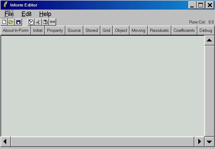
One such button is shown here, for the top panel.
When that button is pressed, the Inform Editor appears.
Similar buttons appear on lower-level panels of the VR-Editor user-interface.
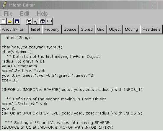
The existing Group 13 statements are viewed here
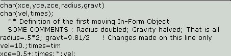
They are then changed by way of Notepad-like editing actions to this.
When they are what the user wants, they are saved.
This action places them in the phxx file which the VR Editor uses to store items which must be written to the final Q1, the relevant part of which is seen here:
  Echo InForm settings for Group 13
  inform13begin
char(xce,yce,zce,radius,gravt)
char(vel,times);
   ** Definition of the first moving In-Form Object
   SOME COMMENTS : Radius doubled; Gravity halved; That is all
radius=.5*2; gravt=9.81/2     ! Changes made on this line only
vel=10.;times=tim
xce=0.5+:times:*:vel:
Now that the PHOENICS Commander, which also employs the Tcl/Tk package, has been adopted as the main introduction to and manager of PHOENICS, these additions to the In-Form Editor will swiftly be made.