When computational fluid dynamics first engaged the attention of engineers, during the 1960s, parabolic flows were a natural focus, because of their relatively small demands on computing power. For example, the Patankar-Spalding program of 1967, which was later developed into GENMIX, concerned two-dimensional parabolic flows, such as boundary layers, jets and wakes.
A later Patankar-Spalding contribution to CFD, of 1973, namely the SIMPLE algorithm, was also applied to three-dimensional parabolic flows in the first instance.
It is therefore not surprising that PHOENICS is equipped with a "parabolic option", the nature and utilisation of which will now be described.
These conditions often prevail in boundary layers, shear layers, jets, wakes, pipes and other conduits, when the Reynolds and Peclet numbers, based upon the cross-stream dimension, are large.
Smoke plumes, flows in not-too-winding rivers, and jet-engine exhausts are practical examples.
Such flows are called parabolic because mathematicians have applied that adjective to the differential equations which describe them, contrasting them with the related but different "elliptic" and "hyperbolic" ones.
The main reason for distinquishing parabolic flows from elliptic ones is that their special features may be exploited so as to reduce greatly the time and expense of the calculations.
This exploitation is effected, in PHOENICS, by setting PARAB = T in the Q1 file. The same applies, incidentally, to hyperbolic flows, which also allow differences to flow downstream only.
Hyperbolic flows are those in which the velocity in the main direction of flow is supersonic, which circumstance prevents the upstream transmission of information in a steady flow. Then the same economies as are associated with parabolic flows, namely unlimited grid-refinement in the z-direction, can be enjoyed.
It is sometimes then said that the "parabolized Navier-Stokes equations are being solved".
Whatever it is called, PHOENICS provides for it.
Click here for the "mathematics of PHOENICS lecture"
The finite-volume equations for parabolic problems differ from the general ones in three respects.
The first is that the term
phiH*aH
  phiP = aE.phiE + aW.phiW + aN.phiN + aS.phiS + aL.phiL + S
         ----------------------------------------------------
            aE + aW + aN + aS + aL + aP
A further, less obvious, difference is the omission of the diffusive component from the coefficient in the term
phiL*aL
The third difference concerns the representation of the pressure force on the z-directed velocity resolute w. The z-wise variations of pressure level, p, are decoupled from the lateral (i.e. x and y) variation of the pressures (which continue to be determined by reference to cell-wise continuity).
The force on the w velocities is taken as
-Dp/Dz .
Because of the absence of the AH term, a single sweep through the integration domain suffices. However, in order that the non-linearity and inter-connectedness of the equations can be adequately represented, a sufficient number of iterations must be conducted at each slab, in order that imbalances in the equations have been adequately reduced; for single-sweep parabolic calculations allow no 'second chance'.
Therefore, instead of the LSWEEP = 50 (say) which is set for an elliptic-flow problem, the corresponding setting in a parabolic-flow calculation would be LITHYD = 50 .
To make one forward step in the integration sweep, it is necessary to hold in computer memory the variables relating to only two slabs, namely (1) the local one, and (2) its immediately-upstream neighbour.
This means that an unlimited number of slabs can be employed without any any increase of computer storage.
This has the advantage that a very-fine-grid solution can be obtained; for all available storage can be used for the cross-stream directions.
In PHOENICS, the predominant direction of a parabolic flow is always the z-direction. Storage is therefore provided only for the current and the low slabs.
Attempts to access "high" values by way of In-Form statements or GROUND coding will therefore fail. So, probably will attempts to access "low" values; for, as soon as a new forward step starts, these are moved into current-step storage as initial guesses.
To instruct PHOENICS to simulate a flow in the parabolic manner, it is first necessary to set PARAB = T in the Q1 file.
LITHYD should be set to a sufficiently high value to ensure convergence. LSWEEP, which is used for that purpose in elliptic problems, has no significance for parabolic flows.
The integer IPARAB also needs to be set in order to indicate how the downstream pressure is to be computed. This differs as between confined and unconfined flows. For the former (IPARAB=0), EARTH calculates automatically what pressure gradient will allow mass-continuity to be satisfied.
IPARAB.GT.1 also allows certain hyperbolic flows to be simulated economically (See PHENC entry: IPARAB). The important case of IPARAB=1 is discussed at length in section 4.4 below.
It is necessary that the lateral dimensions of the domain, i.e. XULAST or YVLAST, vary with with downstream distance so as to:
Users are therefore advised to use instead the In-Form grid-specification statements described here.
Caution is needed when selecting the width-enlargement formulae. Over-rapid enlargement places some cells too far away from the physically-interesting region to be economical; and too slow a rate leads to implausibly-steep profiles near the free-stream boundary. Inspection of the computed profiles, and adjustment of the enlargement-rate formula so as to avoid the extremes, is always advisable until a user has found formulations which always work satisfactorily in his or her circumstances.
It is best to employ solution-adaptive In-Form formulae such as:
When this velocity aproaches the free-stream velocity, the enlargement of the width of the grid is much reduced, as can be seen from the following table, which shows the total enlargement of the grid,when this formula is used, for core-library case 190.
| yrfac | w ratio | YVLAST/YINLET |
| 0.1 | 9.419406E-01 | 1.132596E+00 |
| 1.0 | 9.897953E-01 | 1.450421E+00 |
| 10.0 | 9.985036E-01 | 1.944726E+00 |
| 100.0 | 9.998467E-01 | 2.314851E+00 |
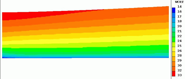
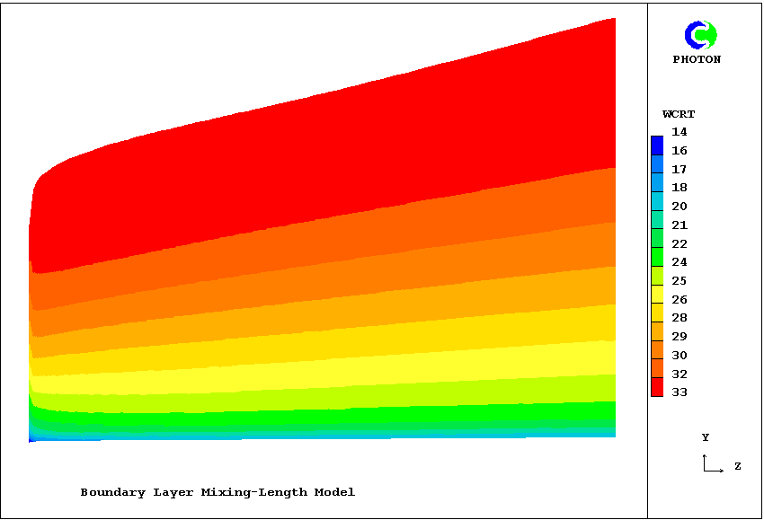
The first of the next two contour diagrams. corresponding to yrfac=0.1, reveals that indeed that factor is too small; for the contours intersect the upper edge. The second, for yrfac=100.0, shows that the enlargement is rather excessive; for a significant region of the upper region has uniform velocity. nevertheless even these extremely different grids produce not-very-different solutions in the important region close to the wall.


Allowance for changes in main-stream velocity are best accomplished by including an additional multiplier in the YRAT (or XRAT) formula, namely wfree_last/wfree_current. This will be illustrated below.
The former may be represented by way of In-Form thus:
MAKE DPDZ is 0.0)
(STORE1 DPDZ is -:rho1:*(:dwfz:)*wfre)
patch(prgrd,volume,1,nx,1,ny,1,nz,1,1)
(source of w1 at prgrd is -dpdz)
What are dwfz and wfre? The following in-Q1 lines answer:
(MAKE wfre is :wfree:)
(STORE1 wfre is :WFREE:+(:dwfz:)*ZZW)
wherein dwfz must have been declared as a PIL variable to represent the (uniform) increase of w1 with z.
As mentioned in section 4.3, the width of the grid should vary with the mainstream velocity. Specifically the width*velocity product should remain constant. The following yrat formula effects this:
Human error being always to be expected, it is wise to check the compatibility of the dpdz and wfre settings. The following image provides such a check by supplying a uniform upstream profile and de-activating the solid-wall boundary condition. The free-stream velocity is caused, by the widening of the grid without diffusional effects to further enlarge the boundary layer, to fall linearly from 33 to 27 m/s.
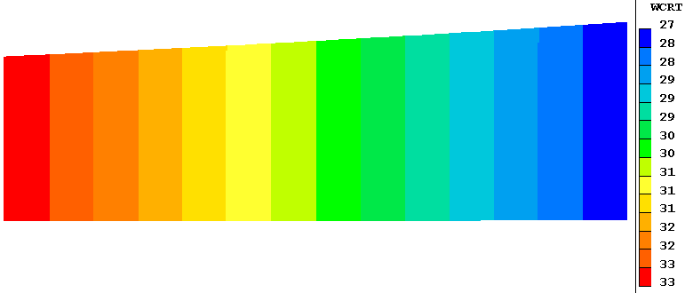
The fact that the contour lines are precisely vertical shows that the wfre formula, which controls the upper edge, is entirely consistent with the dpdz formula, which controls the values below it. This satisfactory check lends credibility to the quite-different contours which are generated when the non-uniform upstream profile and frictional-wall boundary condition are reactivated. It is shown below; and it reveals that the adverse pressure gradient has the effect of causing what is called 'boundary-layer separation', i.e. a zero-velocity region close to the wall.
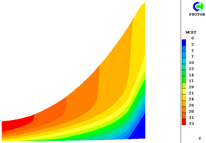
In the case in question, which was derived from input-library case 190, the grid-expansion factor accounted for both diffusional and velocity-reduction effects; and was:
(YGRID of YRAT is 1.0-(:dwfz:*dz/wfre)+:yrfac:*(1.-w1[,ny-1,]/$
:wfree:)*DZ/YVLAST)
The imposed deceleration value, dwfz, was -15 sec-1; and the arbitrary factor yrfac was 0.5. The vertical inclinations of the contours near the upper boundary show that this suffices to spread the grid into the inviscid region; but not too far for accuracy.
In general, because the cells of the parabolic and elliptic grids are likely to be of different sizes, as shown below, interpolation is needed.

In such cases the values of dpdz and dwfz extracted by way of interpolation will vary with the distance z along the surface and will appear as tables of numbers. In-Form allows these to be input into the calculation by way of the PWL (piece-wise-linear functions); but care is necessary in formulating them to ensure that the two functions are wholly consistent.
The above sketch containers a reminder that a two-way interchange of information may take place between the elliptic and parabolic calculations. Thus the elliptic calculation may take place at first, with the assumption that friction at the solid surfaces is absent. Its predicted pressure distribution is for that reason not quite correct. However the ensuing parabolic calculation takes detailed account of friction and can report the so-called 'displacement thickness' of the boundary layer. If this is transmitted back to the elliptic solver, that can repeat its calculation on the assumption that the effective size ot the solid object is larger than it first supposed. Its second flow prediction will be correspondingly more accurate.
Iterative exchanges between the two solvers can ensue; and, because of the relatively weak interactions between them, convergence is likely to be quickly achieved.
(stored var dis is dyv*(1.-w1/:wfree:))
(stored var idis is dis+idis[,-1,]!if(iy.gt.1))
These two simple lines have the effect of placing in the 3D store of the variable called idis, the integral of velocity defect which, carried to the limit, constitutes the displacement thickness. The following fragment of the RESULT file, for dwfz=0.0, shows how its values are represented there:
    IY   IDIS        DIS
    22   1.583E-03   0.0
    20   1.589E-03   1.090E-05
    18   1.573E-03   2.331E-05
    16   1.529E-03   3.747E-05
    14   1.456E-03   5.342E-05
    12   1.349E-03   7.103E-05
    10   1.205E-03   9.013E-05
     8   1.020E-03   1.105E-04
     6   7.927E-04   1.320E-04
     4   5.208E-04   1.551E-04
     2   1.946E-04   1.946E-04
Evidently the displacement thickness can be taken as approx. 1.58E-03 m in this case. [By contrast, the displacement thickness for the above dwfz=-15, boundary-layer-breakaway, case rose to 1.4 E-2 m].No doubt, if the thus-computed value is fed back to the elliptic solver, which thereupon transmits a different pressure distribution to the parabolic solver, the latter will calculate a slightly different displacement thickness next time. Further refinement will however not be justifiable. We are, after all, employing a turbulence model, not to mention the finite number of grid cells; and these are practices are notoriously unreliable.
It is convenient to include the quantity idis among those of which contour diagrams are plotted. Those for the cases cited above are as follows:
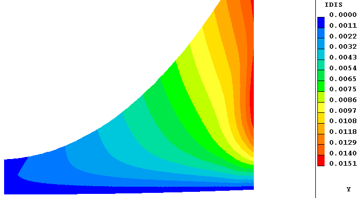
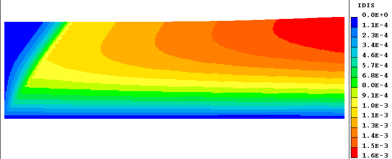
The different behaviours of the separating (left) and non-separating (right) boundary layers are visible at a glance.
Since, by definition, downstream events can have no upstream influence in a parabolic situation, no downstream boundary conditions are needed. Moreover, attempts to provide them may have undesirable effects, because PHOENICS will attempt to apply them at the last slab that it knows about, which is the current one.
Consequently, simply to set PARAB = T, at the end of a Q1 file that had been earlier set up for an elliptic-mode solution, would give an undesired result. For example, the IZ=NZ boundary condition corresponding to a fixed-pressure outlet would prevent any pressure variation at all.
Users who have hitherto used only elliptic-mode (i.e. PARAB=F) settings, are therefore advised to study the parabolic examples in the Input File Libraries.
One consquence of there being no outlet patch at the last high-z surface is that no values of the outflows through it are printed in the RESULT file. Therefore, for parabolic calculations, the significant differences between the "neg sum" and "pos sum" values in the "nett flux" print out might disquiet users familiar only with elliptic flows. The differences do not however indicate poor convergence; they point only to an insufficiency in the print-out provisions.
If PARAB is T, EARTH storage is provided only for the current z-slab and the one preceding it (i.e. the lower slab); as a result, the data file used for PHOTON and EARTH restarts (PHI or PHIDA) contains only data from the last slab.
It can therefore be used for restarts but is not very useful for viewing results with PHOTON. However, a GX... subroutine, GXPARA, has been provided for the creation of PHOTON- readable output files for the graphical representation of the results of parabolic runs. GXPARA is called only when the following setting are made in the Q1 file:
PARAB = T and IDISPA = 1 or greater.
Setting IDISPA to a value greater than one will cause GXPARA to group the slabs in groups of IDISPA, and dumping only the values at the central slab of each group to the output file, thus allowing for economy of space and processing time for problems with a large number of slabs.
Users can also set IDISPB and IDISPC to the first and last slabs, respectively, for which results are to be dumped. The defaults are: IDISPB=1; IDISPC=NZ.
Formatted or direct-access files are created by GXPARA according to whether PHIDA=T or F in has been set in the PREFIX file by the user. Formatted files are named PARPHI, direct-access files PARADA.
If either XULAST or YVLAST is a function of IZ, then a geometry file PARXYZ (formatted) or PARZDA (direct-access) file is also written. PHOTON treats these files as it would the files generated by EARTH for a body-fitted-coordinate problem.
If there are any variables of which the values are not required to be written to PARPHI, the variable name should be set to a 4-character string, the last 2 characters of which are '**'; eg. NAME(R2)=R2**
(NOTE that only PHIDA or PHI should be used for restart runs, NOT PARADA or PARPHI)
An early example: a buoyant smoke plume in a tunnel
The turbulent Bunsen burner with a 14-fluid turbulence model
The plane turbulent mixing layer, with a multi-fluid turbulence model
More recent compressible-flow developments are described below.
Because the flow is partly sonic and partly subsonic, the PIL variable IPARAB has to be set equal to 5 in the Q1 file; and STORE(MACZ) should appear, also, in order that the appropriate testing for Mach Number can be carried out.
The typical succession of higher- and lower-pressure regions is clearly seen in the following pictures, in which the flow is from right to left.
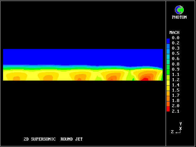
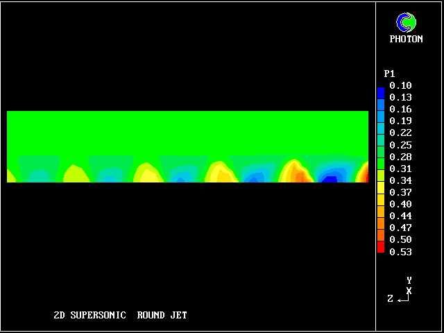
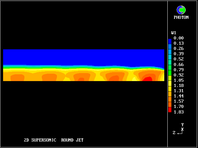
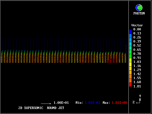
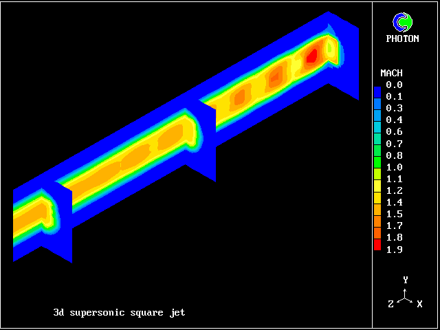
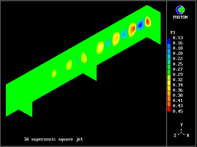
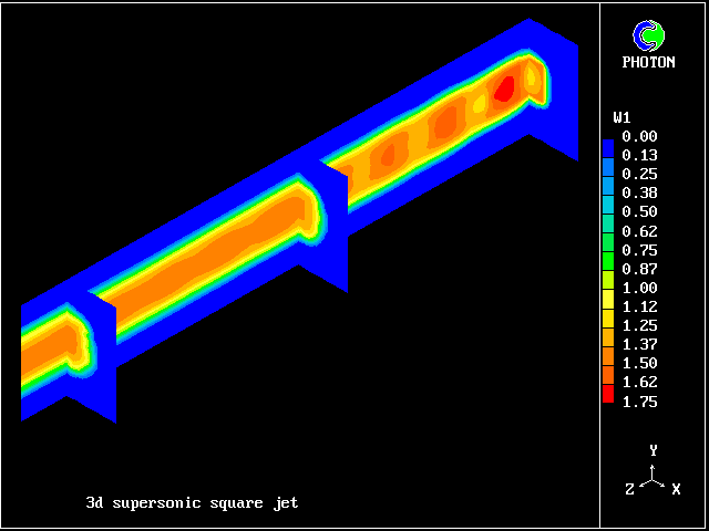
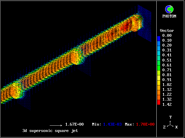
The flow is three-dimensional. The IPARAB and MACZ settings are as before.
The typical succession of higher- and lower-pressure regions is clearly seen in the following pictures.
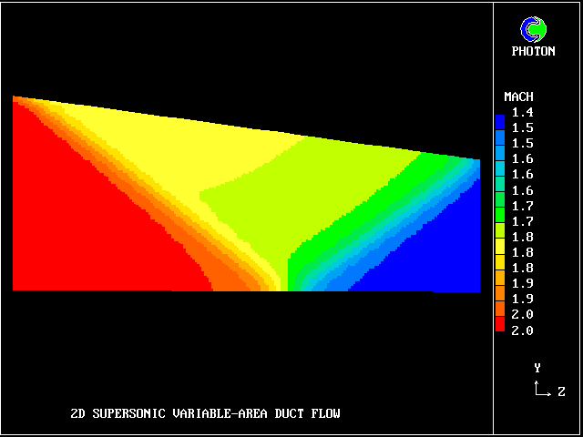
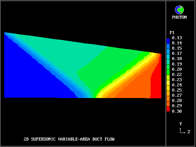
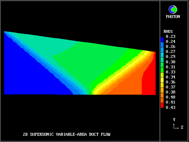
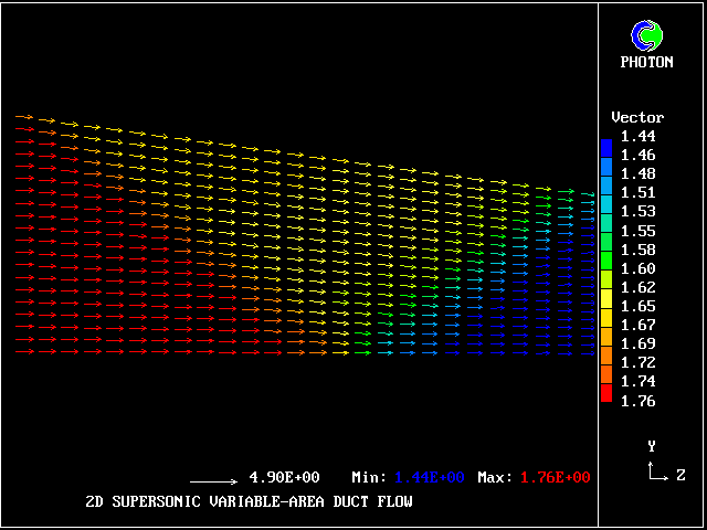
When the flow is wholly supersonic, IPARAB may be set to 4 in the Q1 file; and STORE(MACZ) is not needed.
The following pictures relate to such a flow. The gas enters from the left, in a direction parallel to the lower wall.
A shock wave starts from the upper wall, in order to change the flow direction to accord with the inclination of that wall. This wave crosses the duct and is then reflected from the lower wall.
