Changes Common to VR Editor and VR Viewer
Each Clipping_plane object consists of 3 OpenGL clipping planes. A maximum of two such objects are allowed, as there are only 6 clipping planes. The first Clipping plane object is created at the origin, and clips everything 'behind' it. This is the left-hand object above. The second Clipping plane object is of type 'High end clipping plane' (on the Options tab), and is originally located at the far end of the domain This is the right-hand object above. It clips everything 'after' it. They can be moved and rotated at will to provide a better view inside objects.
Clipping plane objects can also be created from 'Settings - New - Clipping plane' on the Environment Settings menu, or 'Object - New - Clipping plane' on the Object Management Dialog. When created in the Editor, they will be written to the Q1 like all other objects. When created in the Viewer, they will disappear when the Viewer is exited.
Clipping plane objects never affect the grid, and have no influence on the solution.
Double
clicking on the probe or clicking the ![]() icon on the toolbar causes the following dialog to appear:
icon on the toolbar causes the following dialog to appear:
It contains a quick summary of the data at the current probe location. In the Viewer, the current variable can be changed by choosing from the pull down list. The probe location can be moved through the model, either in physical space (X,Y,Z position), or by cell location. When moving in physical space, the 'Cell location' boxes will show the cell centre nearest to the probe. When moving by Cell location, the X,Y,Z boxes will show the physical location of the probe. The 'Set view centre' button centres the view on the probe.
In the Viewer, the Low Spot and High Spot tabs have similar buttons, and the 'Move probe here' button is active. This allows the highest and lowest values to be quickly located and viewed.
The wind object is very closely related to the wind_profile object described here. Only one Wind object is allowed, and it always fills the entire domain. Based on the wind direction it creates inflow boundaries at the domain edges using logarithmic or power law profiles on the upwind faces, and fixed pressure boundaries on the downwind faces. In addition, the upper, or sky boundary can also be made into a fixed pressure boundary.
The 'Ambient pressure' and 'Ambient temperature' entries set the pressure and temperature prevailing outside the domain. These values can be used, if desired, to set the external pressure and temperature at all INLET, WIND, WIND_PROFILE, OUTLET, FAN and PRESSURE_RELIEF objects.
When 'Initialise from ambient' is set ON (the default), the initial values of pressure (P1) and temperature (TEM1) are always made consistent with the ambient values set here.
When 'Set buoyancy from ambient' is ON (the default), the reference temperature for Boussinesq buoyancy is set to the ambient temperature, or for density_difference buoyancy, the reference density is calculated from the ambient pressure and temperature.
Many objects types have a button labeled 'InForm Commands' on their attributes page. This leads to a dialog from which a selection of InForm commands can be attached to the current object. The usual format of an InForm command is as follows:
(KEYWORD of VARIABLE at LOCATION is FORMULA with CONDITION)
The dialog allows such commands to be created with the LOCATION keyword being taken as the name of the current object. InForm commands created in this way are held in the Q1 together with the remaining object attributes.
As an example, the image below shows the settings required to make the inflow mass source and velocity at an INLET a linear function of the Z height.
Object type:
> OBJ, TYPE, USER_DEFINED> OBJ, PATCHES, patch1, patch2, patch3, patch4, patch5
> OBJ, PATCHES, patch6, ... patchnThe PATCHES attribute contains a list of the patch names associated with this object. As many PATCHES lines as needed to hold all the patch names can be used.
All settings relating to the PATCH and COVAL statements linked to a user-defined object are printed in the relevant Group - these can be Groups 11, 12, 13, or 23. The name of the controlling object is written as a guiding comment.
The first location argument of PATCH (usually IXF) is set to -1, to indicate that the patch is to be linked to an object. The remaining five location arguments are zero. As many PATCH commands can be attached to one user-defined object as required.
In earlier (pre-2009) versions the IXF location argument was used to hold the object number. This method is still recognised on reading a Q1, but when the new Q1 is written the object number will be replaced by -1, and the patch name will be echoed in the PATCHES list.
The solver used for each variable can be switched between the default Stone-type solver, and an alternative conjugate-residuals-gradient solver.
The 'Terms in Equations' section has been moved to a separate panel.
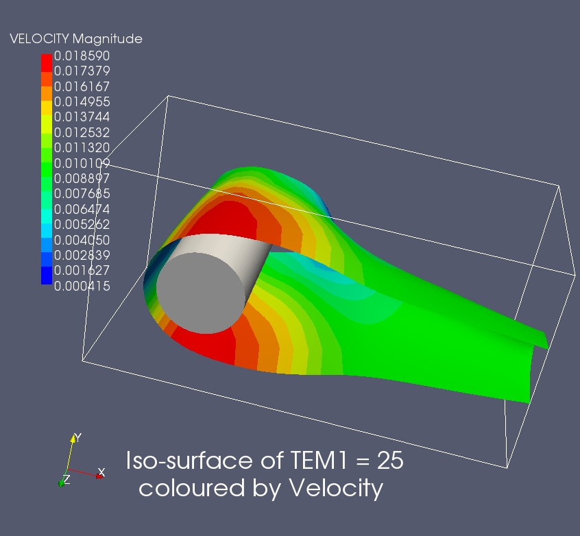
The Earth solver can now output files in VTK format. These files are compatible with the ParaView post-processor available for free download on the web.
In total, two files are involved.
Vtkcentre.vtk contains a grid located at the PHOENICS cell centres. The data is the 'raw' PHOENICS data, apart from the velocities which have been averaged from the cell faces to the cell centres. For PARSOL cut cells, the cell centre locations are the centres of the fluid cells. This zone is suitable for plotting vectors, as the vector tails will be in the same location as in the Viewer.
Vtkvertex.vtk contains a grid located at the PHOENICS cell corners. The data has been averaged from the surrounding cell centres for scalars, or cell faces for vector quantities. The values in PARSOL cut cells are those from the fluid cells. Contours plotted from this zone will fill to the edge of the domain as in the Viewer.
The InForm INFOB command can be used to create a PLANE object, which can act as an angled plate.
The Main Menu in the Viewer is much simpler than in the Editor.

Note that it is only the contour scale, probe value and average value which are changed - the data is left untouched. The probe location is also shown in the selected unit set.