Encyclopaedia Index
1. Introduction
5. Creating data files with a Fortran program
Appendix A - The PHOENICS-VR Colour Pallete
Appendix B - The object orientation matrix
PHOENICS-VR has provided users with a large number of data files for objects ranging from simple shapes such as cubes, cylinders, to complicated objects including gas burners.
The dimensions of all the objects are 1m*1m*1m. Users can load these objects into the VR editor and then modify their dimensions and orientation.
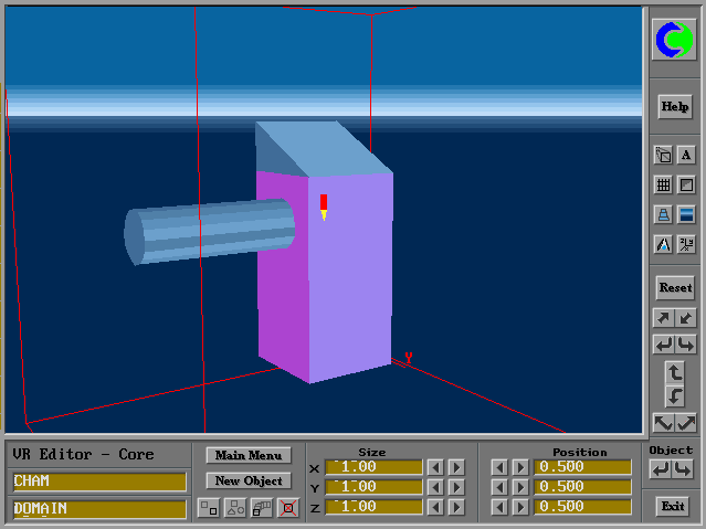
Moreover, simple shapes can be combined to obtain the desired geometry. For example, Figure 1 shows an object formed by a block, cylinder and a wedge.

Fig.1 An object formed by a cylinder and a wedge
Nonetheless, it is sometimes necessary for users to write data files for their own objects, and store the data files in the object data-base for future use.
The rest of the article describes how to write data files which can be accepted by PHOENICS-VR.
An object can be represented by facets distributed on the outer surfaces of the object. In order to write a data file, the first task is to define the object in question by creating facets around its outer surface.
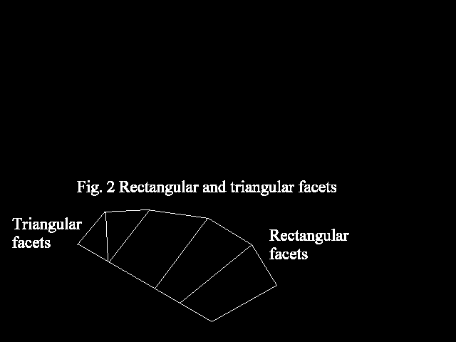
Each facet should be built from four points. Triangular facets can be made by repeating one of the points. Figure 2 shows rectangular and triangular facets distributed on a body surface.
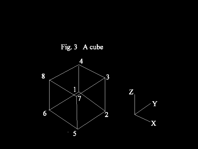
For a simple geometry, the creating of facets is a straightforward task. For example, a cube can be adequately defined by 6 face facets with 8 corner points as shown in figure 3 below.
However, for a complicated geometry such as a burner described in Figure.4, care is needed when creating the facets.
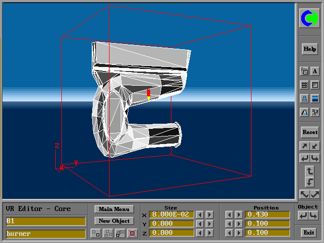
Fig.4 Facet distribution around the surface of a gas burner
It is obvious that more facets are required to represent a curved or skewed or distorted surface than a flat surface.
After the facets have been created, the coordinates of all the points required to build these facets should be given.
As mentioned above, in the data files of PHOENICS-VR, the dimensions of an object are
1m*1m*1m. It is therefore necessary to normalize the actual coordinates of all the points
designated as follows:
Xin = (Xi - Xmin)/(Xmax - Xmin)
Yin = (Yi - Ymin)/(Ymax - Ymin)
Zin = (Zi - Zmin)/(Zmax - Zmin)
Where:
Xin, Yin and Zin are normalized coordinates;
Xi, Yi and Zi are the actual coordinates;
Xmin, Ymin and Zmin are the minimum values of all the actual X , Y and Z coordinates respectively;
Xmax, Ymax and Zmax are the maximum values of all the actual X, Y and Z coordinates respectively.
Figure.5 shows the actual coordinates and the normalized coordinates of an arbitrary shape.
First, let us have a look at the data file for a cube. As described in Figure.3, 6 face facets and 8 corner points are used to define the cube.
The data file contains the following entries:
8 ---> the number of points
0.0000E+00 1.0000E+00 0.0000E+00
1.0000E+00 1.0000E+00 0.0000E+00
1.0000E+00 1.0000E+00 1.0000E+00
0.0000E+00 1.0000E+00 1.0000E+00 ---> normalized coordinates
1.0000E+00 0.0000E+00 0.0000E+00 of the points
0.0000E+00 0.0000E+00 0.0000E+00
1.0000E+00 0.0000E+00 1.0000E+00
0.0000E+00 0.0000E+00 1.0000E+00
6 ---> the number of facets
2 1 4 3 2
5 2 3 7 11
6 5 7 8 4 ---> the point numbers building
1 6 8 4 14 the facets and colour number
8 7 3 4 13
1 2 5 6 15
3 1 3 5 ---> the number of orientations and rotation codes
Examination of the data file suggests that the file can be divided into three parts:
1) a list of normalised coordinates for each point
2) a connectivity list for each facet, showing how the facet is generated from 4 points
3) a rotation code which lists available orientations
Part 1 - The coordinate list
The first line contains an integer (in I6 format), which gives the total number of points (8 in this case). The next lines contain 3 real numbers (in E12.5 format), which are the normalized coordinates.
Note the following rules for entering data:
- The character for the number of points on the top line should not be written beyond the 6th column; for example, a number 8 can be written in the 6th column, but a number 18 should begin with the 5th column and a number 120 should begin with the 4th column and so on;
- The order for entering the coordinates of the points is of no importance; however, once the coordinates have been entered, numbers are allocated to the points: on the first line is the point number 1, on the second the point number 2 and so on;
- The X coordinates should not be beyond the 12th column, the Y coordinates should not be beyond the 24th column and similarly Z coordinates should not be beyond the 36th column; therefore the character length of each coordinates must not exceed eleven.
Part 2
The second part of the data file contains the connectivity information for each facet. The number of facets (6 in this case) is given before a set of lines indicating the point numbers which create these facets. As mentioned above, a facet is always defined by four points; if a facet is formed from three points, then a repeated point number must be entered twice. The numbers are written as integers in I6 format.
The number of the point is the sequence number designated in the first part of the data file and has been described above.
A colour number is given at the end of each line. The colour palette is given in Appendix A.
Again note the following rules for entering data:
Part 3
The orientation code is given here. The number of allowed orientations is specified first in column 3, followed by a list of integer numbers defining the orientations. These numbers end at the sixth, ninth, twelfth column respectively. A complete list of orientation codes is given in Appendix B. Figures 7 and 8 show the effects of changing the orientation.
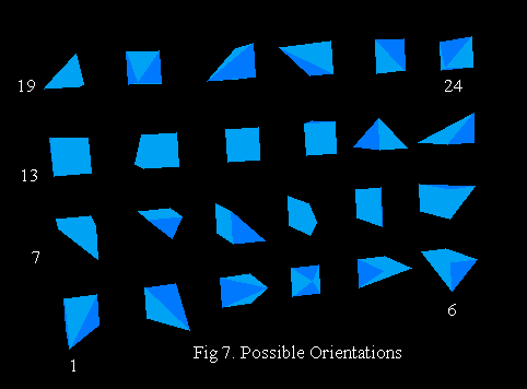
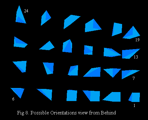
It is sometimes desirable to use a Fortran program to writing the data file for the object in question, especially when the mathematical formula describing the object is known.
For this case, in addition to the coding which create all points and facets coordinates, the following statements must be used in the program to write the data file:
C... Open the file 11, filename.dat: OPEN(11,FILE='FILENAME.DAT',STATUS='UNKNOWN')
C... Write the total number of points, NP, on the
C... first line. The I6 format writes an integer
C... ending at the sixth column
     WRITE(11,'(I6)') NP
C... Write the coordinates of the corner points using a
C... specific format
     DO 1000 I=1,NP
1000 WRITE(11,'(1P3E12.5)') XP(I), YP(I), ZP(I)
C... Write the total number of facets, NFACET, one integer
C... ending at the sixth column
     WRITE(11,'(I6)') NFACET
C... Write the facet instructions: '5I6' means 5
C... integers with 6 columns for each
     DO 1100 I=1,NFACET
1100 WRITE(11,'(5I6)') (IFACET(J,I),J=1,5)
C... Write the clip-art rotation code, and close the
C... file:
     WRITE(11,'(25I3)') 3,1,5,9
     CLOSE(11)
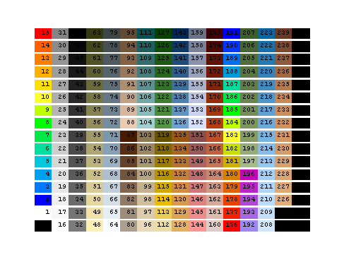
The available colours
Appendix B - The object orientation matrix
All 24 possible directions:
1 XNEW = X YNEW = Y ZNEW = Z
2 XNEW = 1-Y YNEW = X ZNEW = Z
3 XNEW = 1-X YNEW = 1-Y ZNEW = Z
4 XNEW = Y YNEW = 1-X ZNEW = Z
5 XNEW = X YNEW = 1-Z ZNEW = Y
6 XNEW = Y YNEW = 1-Z ZNEW = 1-X
7 XNEW = 1-X YNEW = 1-Z ZNEW = X
8 XNEW = 1-Y YNEW = 1-Z ZNEW = X
9 XNEW = Z YNEW = Y ZNEW = 1-X
10 XNEW = Z YNEW = X ZNEW = Y
11 XNEW = Z YNEW = 1-Y ZNEW = X
12 XNEW = Z YNEW = 1-X ZNEW = 1-Y
13 XNEW = X YNEW = 1-Y ZNEW = 1-Z
14 XNEW = Y YNEW = X ZNEW = 1-Z
15 XNEW = 1-X YNEW = Y ZNEW = 1-Z
16 XNEW = 1-Y YNEW = 1-X ZNEW = 1-Z
17 XNEW = X YNEW = Z ZNEW = 1-Y
18 XNEW = 1-Y YNEW = Z ZNEW = 1-X
19 XNEW = 1-X YNEW = Z ZNEW = Y
20 XNEW = Y YNEW = Z ZNEW = X
21 XNEW = 1-Z YNEW = Y ZNEW = X
22 XNEW = 1-Z YNEW = 1-X ZNEW = Y
23 XNEW = 1-Z YNEW = 1-Y ZNEW = 1-X
24 XNEW = 1-Z YNEW = X ZNEW = 1-Y