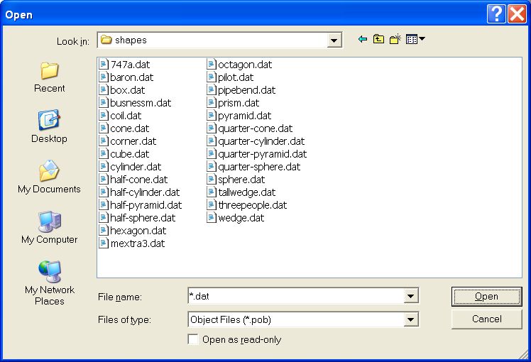
Although this displays only one of several supplied folders, the fact remains that the attempt to provide enough shapes by way of facet-describing .dat files is in principle hopeless; for, all that the VR-Editor can do after importing them is to change the dimensions of the rectangular box which contains them. However, if one of the objects were a hollow cylinder, for example, the ratio of the internal to external diameter would remain the same, no matter how much the object was stretched and squeeezed.
As a consequence, users have in the past been advised to combine two of the available objects in order to create a not-available third. Hollow cylinders, for example, have been created by combining a first solid cylinder with a coaxial second one, of smaller diameter, of which the material is domain fluid.
That many users have been successful in doing so testifies to their admirable ingenuity; but that they were required to exercise it was not something in which CHAM could take pride.
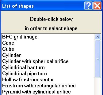
Where, it might be asked, is the previously-mentioned hollow cylinder? Hidden, is the answer, within the class of objects named 'hollow frustrum sector'; for these comprise all solids having a conical exterior surfac, a coaxial conical inner surface, and other faces exposed by two perpendicular-to-axis and two passing-through-axis cutting planes. The following image illustrates what is meant.
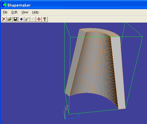
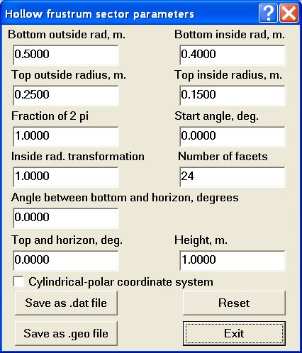
Obviously, a hollow cylinder will be created if the inner and outer radii are the same at the top and the bottom, and if the sector angle is made equal to 360 degrees instead of the 120 degrees shown above. These parameters can be chosen interactively by way of menus such as the following:
Cites designed by not-very-imaginative architects might need only a few of the 'nonahedron' class of object, seen below:
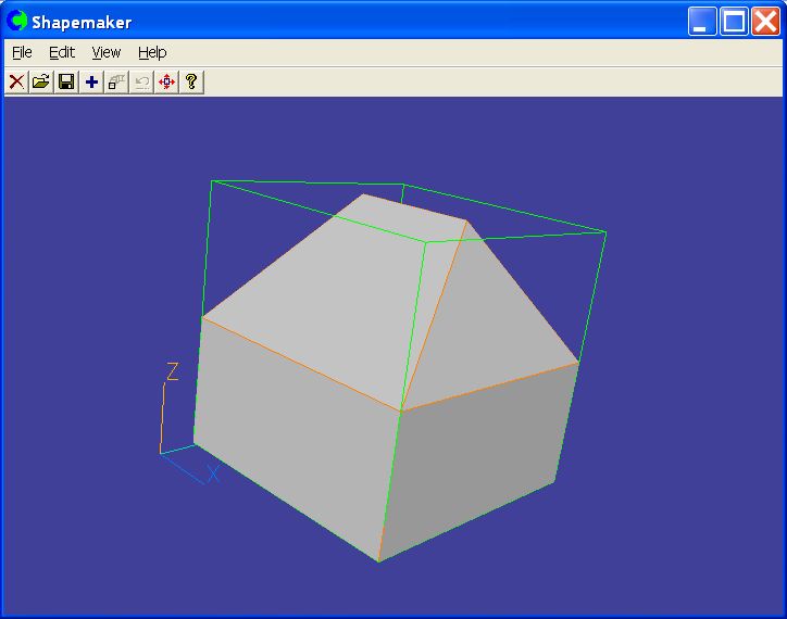
all with the same roof angle and differing only by way of a few length-to-width ratios. Their CFD specialists too may then adopt the prepare-in-advance strategy.
There are two ways of so doing:
ShapeMaker can also be activated from within the PHOENICS VR-Editor.
This interactivity necessarily entails specialist-man-time expense; which can not be tolerated when many runs are to be conducted with objects of the same class; and conducted, as is often the case, by persons who are not CFD specialists. In the majority of cases therefore the command-file method must be adopted.
It can to do so because it describes an object in two distinct ways:
Moreover, whereas a .dat file is only written, a .geo file can be read also. Indeed the command:
But who or what writes the .geo file? A parameterised Q1 can do so, as will now be described.
mesg(about to write fin.geo
write(>fin.geo,shape    compsfrstr)
write(>>fin.geo,height  :ftkn1:)
write(>>fin.geo,heigh2  :ftkn2:)
write(>>fin.geo,heigh3  :ftkn3:)
write(>>fin.geo,borad   :frou1:)
write(>>fin.geo,birad   :fradin:)
write(>>fin.geo,torad   :frou1:)
write(>>fin.geo,tirad   :fradin:)
write(>>fin.geo,tord2   :frou2:)
write(>>fin.geo,tird2   :fradin:)
write(>>fin.geo,tord3   :frou2:)
write(>>fin.geo,tird3   :fradin:)
write(>>fin.geo,f2pi    0.5)
These, when processed by the PHOENICS Satellite module, cause it to write the following file, fin.geo
shape    compsfrstr
height  7.5E-04
heigh2  7.5E-04
heigh3  1.5E-03
borad   0.035
birad   0.017
torad   0.035
tirad   0.017
tord2   0.02
tird2   0.017
tord3   0.02
tird3   0.017
f2pi    0.5
This is a file which ShapeMaker understands, the first line indicating that the required object is of ShapeMaker's composite-frustrum kind shown below:
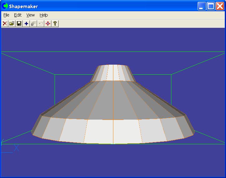
and the subsequent lines indicating what (non-default) parameter values it should use.
The numbers are the evaluations of the quantities :ftkn1: etc which must have been declared in the PQ1, their values having been assigned or calculated higher up in that file.
Immediately below the 'WRITE' instruction in the PQ1 there appears the single line:
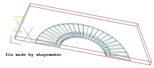
EXEC(t,shap.bat,fin.geo,fin.dat)which causes ShapeMaker to read the fin.geo file and write the fin.dat one. The VR Editor can then reveal what has been created thus:
xpos=xaxis-frou1
ypos=0.
zpos=0.> OBJ,    NAME,        FIN
> OBJ,    POSITION,    :xpos:, :ypos:, :zpos:
> OBJ,    SIZE,        :fdmou:, :frou1:, :ftkns:
> OBJ,    GEOMETRY,    FIN
in which the values of the parameters fdmour, etc had already been assigned. Of course these values can vary from run to run as the formulae in the PQ1 dictate.
(c) shape   compsfrstr     Composite frustrum
height  0.100000       height
heigh2 0.200000       2nd height
heigh3 0.100000       3rd height
borad   1.000000       bottom outside radius
birad   0.100000       bottom inside radius
torad   0.900000       top outside radius
tirad   0.150000       top inside radius
tord2   0.300000       top 2nd outside radius
tird2   0.100000       top 2nd inside radius
tord3   0.200000       top 3rd outside radius
tird3   0.150000       top 3rd inside radius
f2pi    1.000000       fraction of 2 pi, (0-1)
But there follow settings which are supplied for all classes of objects; and these include sizes, positions, rotations, etc
nfacets 24             number of facets
cartes  1              1 for cartesian or 0 for polar
opaque  1              1 for opaque or -1 for transparent facets
nxcopy  1              X number of copies of arrayed shape
nycopy  1              Y number of copies of arrayed shape
xarray  0.000000       shift in X direction of arrayed object
yarray  0.000000       shift in Y direction of arrayed object
xsize   1.000000       X size of placed object
ysize   1.000000       Y size of placed object
zsize   1.000000       Z size of placed object
xpos    0.000000       X position of placed object
ypos    0.000000       Y position of placed object
zpos    0.000000       Z position of placed object
xrot    0.000000       rotation angle about X
yrot    0.000000       rotation angle about Y
zrot    0.000000       rotation angle about Z
tmprt   0.000000       temperature of object
initmp  0.000000       initial temperature of object
prpno   0.000000       material-property index
The above are the default values, which the author of Library case v??? was evidently content to accept; but he could have simplifed his task by transmiting his size and position decisions by way of his .geo file. Corresponding >OBJ.position and >OBJ,size lines would then be placed in the .dat file; and those in the PQ1 would be de-activated.
Further developments now in progress or under consideration include: