Contents
This tutorial supplements the information provided in the general lecture on MOFOR by describing in more detail the structure and content of the MOF file.
A MOF file has two parts, namely: HIERARCHY and MOTION,
The former describes the objects which are present, and how they
are related to each other geometrically and kinematically.
The latter describes how their defining parameters vary with time.
The CHANNELS are the degrees of freedom. They define what type(s) of time-dependent data are defined for this joint; the joint may translate or rotate or both, about any axis.
MOTION is a mandatory key word. It identifies the beginning of the time-dependent part of the MOF file. It is followed by the line specifying the number of Frames. They are the numbers of time moments at which data are given. The number of Frames may be bigger or smaller than the number of time steps of PHOENICS, but they are all equal in size.
The next line, Frame Time, is the time separation of each set of data. For obvious reasons the total time of the particular set of data is equal to (Frames-1)*Frame Time.
There follows the numbers of frames sets of data; the number of values per line are defined by CHANNELS for each ROOT and JOINT objects as hierarchy specifies.
In what follows the number of MOF files will be exemplified and explained in details.
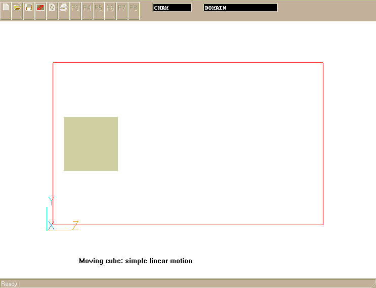
The task is to give a 2D rectangular object called "BLOCK" a uniform velocity of 3m/s in Z-direction of computational domain starting from a given initial position of the object.
The hierarchy part of MOF file is as follows:
HIERARCHY
UNITS METRES
ROOT Cham
{
        JOINT BLOCK
        {
                CHANNELS 1 Zposition
                End Site
        }
}
Only one of the CHANNELS is defined - the movement is along Z-axis.
The initial position and the sizes of the BLOCK are specified in the
Q1 file.
The time-dependent part of the data reads:
MOTION
Frames:     2
Frame Time: 1.
0.
3.
The Motion section defines the time-dependent positions. The file contains 2 sets of positions. At time = 0, Z-position is 0 (plus the offset automatically calculated from initial position of the BLOCK in CFD domain). At time = 1 sec, Z-position is 3 m, which corresponds the velocity of 3 m/s.
Click here to view the animated motion of the object through computational domain (velocity vectors are not shown).
The complete MOF file can be downloaded from here.
To run the simulation:
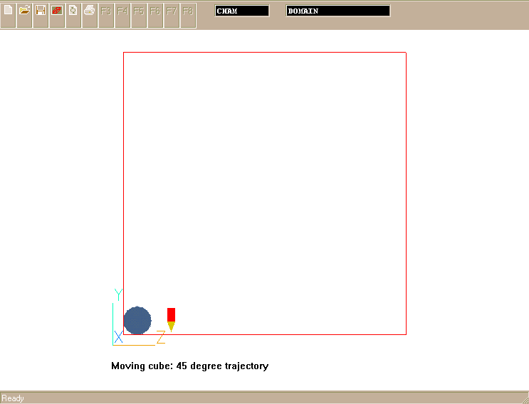
The task is to define a motion of a 2D, Y-Z, circular object called "CYLINDER" following a prescribed linear trajectory of 45 degree climbing. The velocity of the object is, therefore, uniform and the components in Y- and Z-direction are given as 4 m/s. The object starts from a stationary position at the low-south corner of computational domain.
The hierarchy part of MOF file is as follows:
HIERARCHY
UNITS METRES
ROOT Cham
{
        JOINT CYLINDER
        {
                CHANNELS 2 Yposition Zposition
                End Site
        }
}
Two CHANNELS are defined - the movement is along Y- and Z-axis. The initial position and the sizes of the CYLINDER are specified in Q1 file.
The time-dependent part of the data reads:
MOTION
Frames:     2
Frame Time: 1.
0.    0.
4.    4.
The Motion section defines the time-dependent positions. The file contains 2 sets of positions arranged in two columns: first column is for Y- and second one is for Z-position. At time = 0, Y- and Z-positions are 0 (plus the offset automatically calculated from initial position of CYLINDER in CFD domain). At time = 1 sec, Y- and Z-positions are 4 m, which correspond the velocity components of 4 m/s.
Click here to view the animated motion of the object through computational domain (velocity vectors are not shown).
The complete MOF file can be downloaded from here.
To run the simulation:
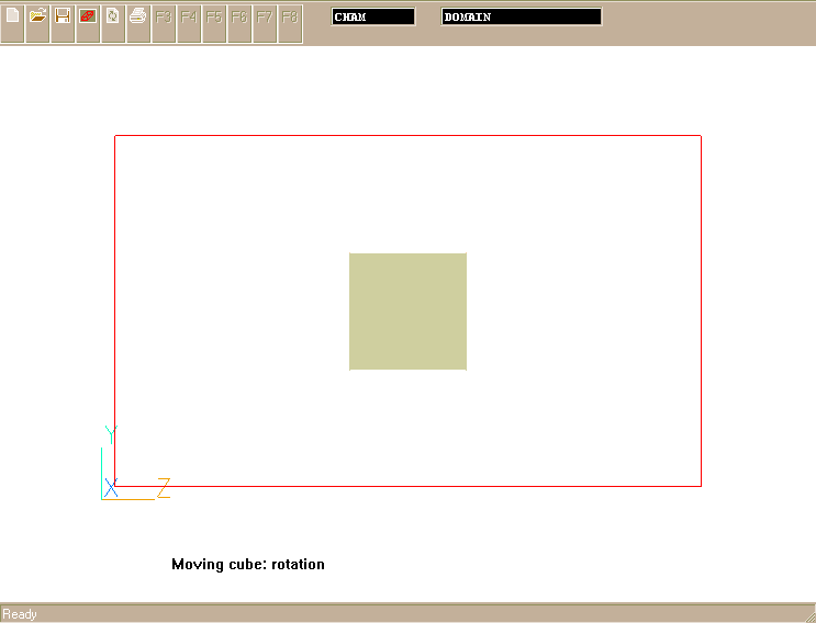
The task is to define a rotation of a 2D, Y-Z, rectangular object called "BLOCK" with angular velocity of 30 rpm (revolutions per minute). The rotation is about X-axis of object centre of mass and starts from its stationary position at the middle of computational domain.
The hierarchy part of MOF file is as follows:
HIERARCHY
UNITS METRES
ROOT Cham
{
        JOINT BLOCK
        {
           OFFSET  0.0 1.5 2.5
                CHANNELS 1 Xrotation
                End Site
        }
}
The OFFSET defines the position of the rotation axis relative to the ROOT frame: it places the axis in the middle of a given computational domain of 1x3x5 m. Only one of the CHANNELS is defined - the rotation about X-axis.
The time-dependent part of the data reads:
MOTION
Frames:     2
Frame Time: 1.
0.
180.
The Motion section defines the time-dependent positions. The file contains 2 sets of positions. At time = 0, angular position of rotation is 0. At time = 1 sec, angular position is 180 degrees, that gives the angular velocity of 0.5 revolution per second or 30 rpm as required.
Click here to view the animated motion of the object through computational domain (velocity vectors are not shown).
The complete MOF file can be downloaded from here.
To run the simulation:
The case exemplifies the specification of the attributes for composite movement: the translation of rotating block. It results in the effect of the rolling 2D rectangular object with the longitudinal (Z-direction) velocity component of 3 m/s and the angular rotation about block centre line (X-axis) of 30 rpm. The movement starts from the initially steady position defined in the Q1 file.
The hierarchy part of MOF file is as follows:
HIERARCHY
UNITS METRES
ROOT Cham
{
        JOINT BLOCK
        {
           OFFSET  0.0 1.5 0.7
                CHANNELS 2 Zposition Xrotation
                End Site
        }
}
The OFFSET defines the position of the rotation axis relative to the ROOT frame: it places the X-axis in the middle of BLOCK initial position. Two CHANNELS are defined - the movement along Z-axis and the rotation about X-axis.
The time-dependent part of the data reads:
MOTION
Frames:     2
Frame Time: 1.
0.        0.
3.0       180.
The Motion section defines the time-dependent positions. The file contains 2 sets of positions. At time = 0, the longitudinal and angular positions are both 0. At time = 1 sec, the Z-position is 3m and angular position is 180 degrees, which give the translation velocity of 3m/s and angular velocity of 0.5 revolution per second or 30 rpm as required.
Click here to view the animated motion of the object through computational domain (velocity vectors are not shown).
The complete MOF file can be downloaded from here.
To run the simulation:
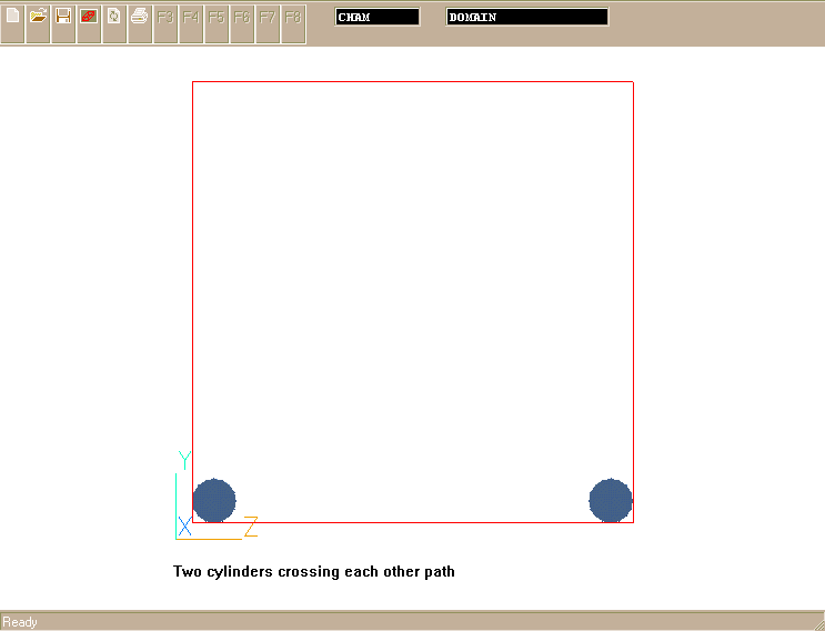
The case exemplifies the setting-up the attributes for the independent movements of two objects following their own linear trajectories in 2D, Y-Z, computational space.
The movement of the first object, called CYL1, starts from its stationary position at the low-south corner. The velocity of CYL1 is uniform and the components in Y- and Z-direction are both given as 4 m/s.
The second object, CYL2, starts at high-south corner of the domain and follows the linear trajectory crossing the one of CYL2. It has the constant velocity component of -3 m/s in Z-direction and 3 m/s in Y-direction.
The hierarchy part of MOF file is as follows:
HIERARCHY
UNITS METRES
ROOT Cham
{
        JOINT CYL1
        {
                CHANNELS 2 Yposition Zposition
                End Site
        }
        JOINT CYL2
        {
                CHANNELS 2 Yposition Zposition
                End Site
        }
}
Two CHANNELS are defined for each object - the movement is along Y- and Z-axis. The initial position and the sizes of the objects are taken from the Q1 file.
The time-dependent part of the data reads:
MOTION
Frames:     2
Frame Time: 1.
0.   0.     0.   0.
4.   4.     3.  -3.
The Motion section defines the time-dependent positions. The file contains 2 sets of positions arranged in four columns.
The first two columns are for CYL1: first one defines Y- and second one defines Z-position. At time = 0, Y- and Z-positions are 0 (plus the offset automatically calculated from initial position of CYL1 in CFD domain). At time = 1 sec, Y- and Z-positions are 4 m, which correspond the velocity components of 4 m/s.
The next two columns are for CYL2: third one defines Y- and the fourth one defines Z-position. At time = 0, Y- and Z-positions are 0 (plus the offset automatically calculated from initial position of CYL2). At time = 1 sec, Y-position is 3 m, which corresponds the velocity components of 3 m/s. In contrast, Z-position is set as -3 m to provide -3 m/s for the velocity component in that direction as required.
Click here to view the animated motions of the objects through computational domain (velocity vectors are not shown).
The complete MOF file can be downloaded from here.
To run the simulation:
The case exemplifies the setting-up the attributes for the connected movements of two objects following their relative rotation in 2D, Y-Z, computational space.
The movement of the first object, called BLOCK, starts from its stationary position as a vertical wall with its base placed next to the middle of the bottom domain boundary. BLOCK is allowed to fall. It does so by rotating clockwise about X-axis of its south-high corner. The angular velocity of the fall is 75 degrees per second.
Initially, the second smaller object, TIP, sits stationary on the top of BLOCK and can be regarded as a part of the wall. Once the whole wall starts to fall, it cracks and TIP begins to move in opposite direction by rotating counterclockwise about X- axis of the north-low corner of the BLOCK. The angular velocity of the TIP relative to the BLOCK is 180 degree per second.
The hierarchy part of MOF file is as follows:
HIERARCHY
UNITS METRES
ROOT Cham
{
  JOINT BLOCK
   {    OFFSET  0.0 0.0 2.1
        CHANNELS 1 Xrotation
     JOINT TIP
       {  OFFSET  0.0 2.5 -0.5
          CHANNELS 1 Xrotation
        End Site
       }
   }
}
Two JOINTS are defined: BLOCK is a parent joint, and TIP is the BLOCK's child.
The OFFSET of BLOCK defines the position of the rotation axis relative to the ROOT frame: it places the origin of parent related coordinate frame at the south-high corner of BLOCK initial position. Only one of the CHANNELS is defined for parent JOINT- the rotation about X-axis.
The OFFSET of TIP defines the position of the rotation axis relative to the BLOCK frame: it places the origin of its coordinate frame at the north-low corner of BLOCK initial position. Only one of the CHANNELS is defined for child JOINT- the rotation about X-axis.
The time-dependent part of the data reads:
MOTION
Frames:     2
Frame Time: 1.
0.     0.
75.    -180.
The Motion section defines the time-dependent positions. The file contains 2 sets of positions arranged in two columns.
The first column is for parent, BLOCK, to define its angular position in degrees of rotation. At time = 0, there is no rotation, so that the angular position is 0. At time = 1 sec, the angular position is 75 degrees. It gives the required fall velocity. The angle is positive as needed for clockwise direction of rotation.
The next column is for child, TIP to define its angular position in degrees of rotation. At time = 0, there is no rotation, so that the angular position is 0. At time = 1 sec, the angular position is -180 degrees. It gives the required velocity of TIP rotation. The angle is negative to provide counterclockwise direction of rotation.
Click here to view the animated motions of the objects through computational domain (velocity vectors are not shown).
The complete MOF file can be downloaded from here.
To run the simulation:
Impellers are the units one most commonly associates with stirred reactors. The particular design considered here consists of the ROD, mounted on rotating vertical SHAFT. The rod carries two PADDLEs, which agitate the flow. The paddles are allowed to rotate in different directions about the axis of the rod. As the impeller rotates it forces the surrounding fluid to rotate with it. The design with rotating paddles is used when "in-depth" mixing is a must.
The task is to define connected movements of SHAFT-ROD-PADDLEs assembly following their relative rotation in 3D computational space. The angular velocity of the shaft is 15rpm. The blades rotate with the same velocity clockwise and counterclockwise, respectively.
The hierarchy part of MOF file is as follows:
HIERARCHY
UNITS METRES
ROOT Cham
{
  JOINT SHAFT
   {  OFFSET  0.15 0.25 0.25
      CHANNELS 1 Xrotation
   JOINT ROD
    JOINT PADDLE1
     {  OFFSET  0.0 0.0 0.0
        CHANNELS 1 Yrotation
        End Site
     }
     JOINT PADDLE2
      {  OFFSET  0.0 0.0 0.0
         CHANNELS 1 Yrotation
         End Site
      }
   }
}
Four JOINTS are defined: SHAFT is a parent joint, and ROD, PADDLE1 and PADDLE2 are the SHAFT's children.
The OFFSET of SHAFT defines the position of the rotation axis relative to the ROOT frame: it places the origin of parent related coordinate frame at the middle of the SHAFT bottom face of its initial position. Only one of the CHANNELS is defined for parent JOINT- the rotation about X-axis.
The ROD rotates about the same axis and has no freedom to move relatively to SHAFT. That is why the RODs definition section is completely omitted here. The OFFSETs of both PADDLEs are also zero: both rotates about the same origin, but their CHANNELs should indicate that it is Y-axis they rotate about.
The time-dependent part of the data reads:
MOTION
Frames:     2
Frame Time: 1.
0.      0.       0.
90.     90.     -90.
The Motion section defines the time-dependent positions. The file contains 3 sets of positions arranged in two columns.
The first column is for parent, SHAFT, to define its angular position in degrees of rotation. At time = 0, there is no rotation, so that the angular position is 0. At time = 1 sec, the angular position is 90 degrees. It gives the required 15 rpm. The angle is positive as needed for clockwise direction of rotation. There is no need for the ROD time data because it is a child which has no associated CHANNELS.
The next column is for second child, PADDLE1, to define its angular position in degrees of rotation. At time = 0, there is no rotation, so that the angular position is 0. At time = 1 sec, the angular position is 90 degrees. It gives the required velocity of PADDLE1 rotation about Y-axis of the SHAFT. The angle is positive as needed for clockwise direction of rotation.
The third column is for third child, PADDLE1, to define its angular position in degrees of rotation. At time = 0, there is no rotation, so that the angular position is 0. At time = 1 sec, the angular position is 90 degrees. It gives the required velocity of PADDLE1 rotation about Y-axis of the SHAFT. The angle is negative to provide counterclockwise direction of rotation.
Click here to view the animated motions of the objects through computational domain (velocity vectors are not shown).
The complete MOF file can be downloaded from here.
To run the simulation:
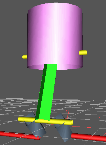
The model of the mechanism schematics of which is shown here consists of the followings:
The crankshaft is the lowest long rod; the cranks are the pair of grey rods; the connecting rod is the long rod up to the large vertical piston. The long narrow rod at the end of the cranks shows the position of the extra joint (the Big End) preventing the connecting rod interfering with the crank joints. The top of the connecting rod is the Little End joint which links onto the piston.
The rotation rate of the engine (the crankshaft) is assumed constant; so the motion of the crankshaft is a simple rotation about the Z axis. Its angular position is:
Angb = omega*time
The position of the end of the crankshaft of radius r (relative to the crankshaft) is
(xb,yb) = (r.sin(Angb), r.cos(Angb))
The top end of the connecting rod moves along a line of constant x & y (x,y=0,0). Its z position is a function of the crankshaft rotation. The top end of the connecting rod is at a constant distance from the end of the crankshaft; its position is:
zc = yb+sqrt(lc^2-xb^2).
The value lc is the length of the connecting rod, xb the position of the end of the crankshaft (given above). The angle of the connecting rod (relative to the world) is derived from the crankshaft x coordinate and the difference between the top of the connecting rod and the y coordinate of the crankshaft.
Angc = atan(zc-yb, xb)
The angle relative to the crankshaft (this is the angle required by the hierarchy) is:
AngCC = Angc-Angb
The piston has zero rotation relative to the world, this requires its orientation relative to the connecting rod to be (-Angc), and relative to the connecting rod angle
Angp=(-Angc) = -AngCC+Angb.
Thus just 3 angles specify the full description of the piston & its linkage.
The hierarchy part of MOF file is as follows:
HIERARCHY
UNITS METRES
ROOT BLOCK
{
	OFFSET	0.000	0.00	0.00
    CHANNELS 0
    ROOT CRANKS
    {
		OFFSET	0.2000	0.1500	0.00
		CHANNELS 1 Zrotation
		JOINT CRANKSHA
		{  # at radius = 0.1m
			OFFSET	0.00	0.1	0.00
			CHANNELS 0
			JOINT BIGEND
			{  # offset to the centre of piston
				OFFSET	0.00	0	0
				CHANNELS 1 Zrotation
				JOINT CONROD
				{  # crank length = 0.25m
					OFFSET	0.00	0.25	0.00
					CHANNELS 1 Zrotation
					End Site
					{  # piston itself = c. 4 inches, =0.09m
						OFFSET	0.0	 0.09	 0.000000
					}
				}
			}
		}
    }
}
The OFFSET is the position of the origin of the coordinate system relative to its parent. The example ROOT joint ('crankshaft') is offset by 0.2, 0.15, 0.1 meters from the world (0,0,0) - this places it in the centre of the CFD domain (defined in the q1 file).
The ROOT joint rotates about the Z axis -this is the angle of the crankshaft, and hence of the cranks.
The CHANNELS define what type(s) of time-dependent data are defined for this joint; the joint may translate or rotate or both, about any axis (eg Zrotation means that rotation about the Z axis is defined in the time section).
The Joint 'Cranks' has a length of 0.1 m - that is the distance of the 'Big End' joint from the crank shaft. When there is no rotation the Cranks start at (0.2, 0.15, 0.18) and end at (0.2, 0.25, 0.18). The Cranks joint has no time.
The 'Big End' joint is offset by 0.08 meters perpendicular to the system stopping the connecting rod from interfering with the Big End joint. The Big End has one time-dependent data - a rotation about the Z axis (relative to the cranks) data.
The connecting rod is 0.25 m long - it has to be longer than the Big End so that the piston can remain on the axis of the engine- and has rotation about the Z axis (relative to the 'Big End', and hence relative to the crankshaft). The 'connecting rod' rotation specifies the rotation of the Piston relative to the 'connecting rod'.
The piston (or 'End Site') is of length 0.09 meters.
The time-dependent part of the data reads:
MOTION
Frames:     48
Frame Time: 0.001
0 0 0

9 -12.58755762 3.587557617
18 -25.10030723	7.100307227
(….. total of 48 lines with data defined in the hierarchy)
Frames specify that there will be 48 times at which data is given. Frame Time - the time separation of each set of data.
There follows the number of frames (48) sets of data; the hierarchy specified that only 3 angles were required, so there are 3 values per line of data.
The rotation angles at time = 0 are (0,0,0). At time 0.00005 sec (9, -12.58755762, 3.587557617).
Click here to view the animated motions of the objects through computational domain (velocity vectors are not shown).
The complete MOF file can be downloaded from here.
To run the simulation: