The aim of this tutorial is to show:
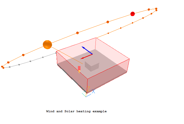
The full geometry of the case is shown in Figure 1 below.

Figure 1. The geometry of the Wind and Solar Heating example
The wind is blowing from the East (indicated by the red arrow) with a reference velocity of 10 m/s at 10m above the ground. The ground roughness height is 0.1m, suitable for low crops, occasional large obstacles. The external pressure is 1 atmosphere (1.01325bar) and the air temperature is 20C. The temperature of the earth is 10C, and the sky 0C. The date is 1st June, and the time of day is 15:00hrs (3pm). The latitude is 51N - around London, UK. The direct solar radiation is 500W/m2, and the diffuse radiation is 100W/m2.
A complete step-by-step guide, showing how to set the case from the default mode of operation, is provided below.
From the system level:
To enter the PHOENICS-VR environment, click on the PHOENICS icon on the desktop, or click on Start, programs, PHOENICS, PHOENICS.
From the commander level:
To enter the PHOENICS-VR environment, click on the 'Run vre' icon in the left column.
In PHOENICS-VR environment:
Start with an 'empty' case - click on 'File' then on 'Start New Case', then on 'Core', then click on 'OK'; to confirm the resetting.
To enter VR Editor:
This is the default mode of operation.
Set the domain Size, and activate solution of variables
Click on 'Main Menu' and set 'Wind and Solar Heating Example' as the Title.
Click on 'Geometry'.
Set the X and Y domain sizes to 150m and the Z domain size to 50m. Click OK to close the Grid mesh settings dialog.
Click on 'Models'. Activate the Energy Equation in Temperature form.
Activate the IMMERSOL Radiation model. Click on 'Settings' for the radiation model and activate the storage of the radiative energy fluxes. These can be used later to analyse the radiative heat flow. Click 'Previous panel'.
Click 'Properties'. Now that temperature is active, we can use the Ideal Gas Law for the air density. This provides a better representation of buoyancy effects. Click on the button next to 'Current domain material is'. Click 'Gases', then 'OK'. From the list of gases select '2 Air using Ideal Gas Law, STP' then click OK. Note that the ambient temperature is defaulted to 20C, and the ambient pressure to zero relative to 1bar. These values do not need to be changed for this tutorial.
We need to activate buoyancy effects. Click on 'Sources'. Turn 'Gravitational forces' on. The reference density will be automatically deduced from the ambient temperature and pressure. Ensure that the gravitational acceleration is along the correct axis and is pointing in the correct direction (here -9.81 in Z).
All other settings can remain at their default values for now. Click 'Top menu' and 'OK' to return to the graphics screen.
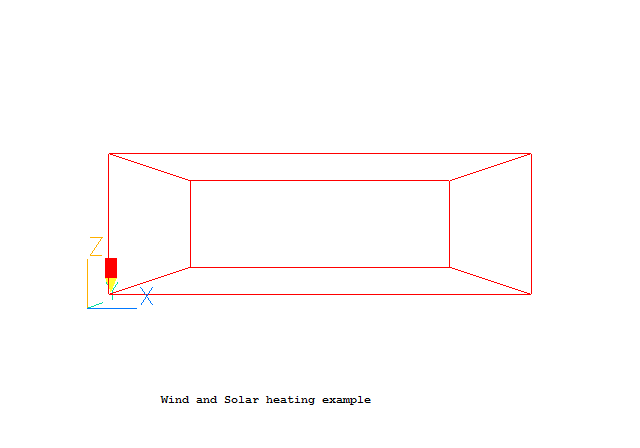
The domain will no longer fit the screen. On the toolbar, click the down arrow next toand select 'Fit to window'. The screen should look like this:
Create the WIND
Click on
on the VR-Editor panel (or the O icon on the tool bar) to bring up the Object Management Dialog; and then on 'Object', 'New', 'New object', 'Wind'.
Change the name to WIND.
Click 'Attributes' to set the wind speed and temperatures.
Change the wind direction to 'East' by selecting from the list of directions. For a direction not on the list, select 'User' and then type in the wind direction. The required wind speed, 10m/s, is the default so does not need to be changed. The reference height of 10m will be measured from the first open cell, i.e. from the top of the object representing the ground.
The temperature is set to 20C, which was taken from the 'Ambient' condition. This was defined to be 20C on the Main Menu - Properties panel seen earlier.
The pressure is set to 101325 Pa, which was taken from the 'Ambient' + 'Reference' pressure values on the Main Menu - Properties panel seen earlier.
If the external pressure is changed here, the reference pressure will be reset to the new value. If the external temperature is changed, the ambient temperature will be reset to the new value. On exit from this dialog, the reference density for buoyancy will be automatically recalculated to be consistent with the set pressure and temperature.
Change the 'Effective roughness height' to 'Low crops, occasional large obstacles'. For a roughness height not on the list, select 'user' and enter the value directly. The roughness height for this type of obstacle is 0.1m.
Set 'Include open sky' to Yes. This will create an addition pressure boundary at the top of the domain and will help anchor the velocity at the top of the domain to the free stream velocity. Set 'External radiative link' to 'Yes' and set the external temperature to 0C. This is in effect the sky temperature, which is always lower than ambient.
Set 'Include ground plane' to Yes, and set the ground temperature to 10C. Later in this tutorial we will create a blockage object covering the bottom of the domain, thus the ground temperature setting here, at the bottom of the domain, will determine the temperature 5m underground.
Activate storage of the Wind Amplification Factor(WAMP). This will create a new 3D store called WAMP, which can be plotted in the Viewer once a solution has been obtained. The wind amplification factor is defined as the local air velocity divided by the incoming wind speed at the reference height.
Click 'OK' twice to return to object management.
Create the SUN
Click on 'Object', 'New', 'New object', 'Sun' in the Object Management Dialog.Change the name to SUN.
Click 'Attributes' to set the solar parameters.
Set 'Get North and Up from WIND' to Yes. This will ensure that the sun and wind share the same domain orientation relative to North.
Set the direct solar radiation to 1000W/m2 and the diffuse radiation to 100W/m2.
Set the date to 1 June, and the time to 15 hrs.
Click on 'Optional extra output'. Activate storage of the illumination flag (LIT), and the total heat source per unit area (#QS2). This creates two additional 3D variables called LIT and #QS2. Eventually LIT will contain the solar illumination, and #QS2 will contain the solar heat load in W/m2.
Click 'OK' three times to return to object management.
Create the object representing the ground
Click on 'Object', 'New', 'New object', 'Blockage' in the Object Management Dialog.
Change the name to SOIL.
On the 'Size' tab set the X and Y sizes to 'to end' and the Z size to 5.0m.
Back on the 'General' tab click 'Attributes' to set the properties of this blockage.
Set the material type to 'Solids' and select '131 Stone chippings' for the material.
Set the roughness to 'User', and the roughness height to 0.1m. Choose 'Fully rough' as the wall function law. These settings match the settings made for the Wind object above.
Set the 'Solar absorption' to 0.5. Only 50% of the solar radiation will be absorbed by the ground object, the remained is assumed to be reflected back to the sky and surroundings. Click 'OK' to close the Attributes dialog.
Click 'OK' to close the specification dialog and return to Object Management.
Create the object representing the Building
Click on 'Object', 'New', 'New object', 'Blockage' in the Object Management Dialog.
Change the name to BUILDING.
On the 'Size' tab set the X and Y sizes to 30.0m and the Z size to 25.0m.
On the 'Place' tab set the X and Y positions to 60.0m and leave the Z position at 0.0m. This will position the building in the middle of the domain, penetrating through the ground.
Back on the 'General' tab click 'Attributes' to set the properties of this blockage.
Set the material type to 'Solids' and select '115 Brickwork (outer leaf)' for the material. This material is not really correct, as it implies that the entire building is solid brick. In reality the properties should be adjusted to account for the composition of the building, but this is too advanced for this simple tutorial.
Set the 'Solar absorption' to 0.2. Only 20% of the solar radiation will be absorbed by the building, the remained is assumed to be reflected back to the sky and surroundings. Click 'OK' to close the Attributes dialog.
Click 'OK' to close the specification dialog and return to Object Management.
Tilt the view down, and push back until the entire solar circle is visible. The screen should now look like this:
The blue arrow points North, and the red arrow indicates the wind direction relative to North. The large orange ball shows the current sun position. The smaller orange balls show the sun position at each hour during daylight, and the grey balls show the sun position at each hour during the night. The red ball shows the sun position at midday.
Set the grid:
Click the 'Wireframe' toggle
to make all the objects display in wire-frame. This will make it easier to see the mesh. On the toolbar, click the down arrow next to
and select 'Fit to window', then 'Nearest head-on.
Click on the 'Mesh toggle' button
. The default mesh will appear on the screen.
The orange lines are region lines,and denote the edges of the bounding boxes of each object. The blue lines are ordinary grid lines introduced by the auto-mesher.
Click anywhere on the image, and the 'Gridmesh settings' dialog box will appear.
The grid in all three directions is set to 'Auto'. For this case it gives approximately 35 cells in X and Y and 40 in Z. This will suffice for the tutorial, though it would not be enough for a 'real' calculation. The grid is too coarse to pick up the details of the flow.
If the geometry of the building is more complex, the grid must also be sufficiently fine to pick up the major details otherwise the shading detection will not work properly.
Click the 'Mesh toggle' button again to switch off the grid display.
Set the remaining solution-control parameters:
Click on 'Main Menu' and then on 'Numerics'.
The default number of iterations is 1000. This is more than enough to determine whether a model has been set up correctly, but is not always enough to obtain an accurate solution.
Reset the total number of iterations to 200. The default automatic relaxation is too conservative for this simple case. Click 'Relaxation control'. Change the 'reference length' from the default 1.0m to 50.0m (1/3 of the domain size). For more complex geometries with more buildings it can be safer to leave the reference length at the default.
Click on 'Previous panel' then 'Initialisation'. The default initial values are 1E-10, in effect 0. The WIND object will automatically initialise the X and Y direction velocities to the wind profile. It will also set the initial KE and EP to the values corresponding to the chosen wind profile.
Click on 'Top menu' to return to the top menu.
Click on 'OK' to exit the Main Menu.
Setting the Probe Location
Before running the solver,it is a good idea to place the probe in a suitable place to monitor the convergence of the solution. Too close to an inlet, and the value will settle down very quickly before the rest of the solution. Placed in a recirculation zone, it may still show traces of change even though the bulk solution is converged. In this case, somewhere downstream of the building is fine.
Click on the probe icon
on the toolbar or double-click the probe itself, and move the probe to X=30.0, Y=75.0, Z=7.0.
In the PHOENICS-VR environment, click on 'Run', 'Solver'(Earth), and click on 'OK' to confirm running Earth.
In the PHOENICS-VR environment, click on 'Run', 'Post processor',then GUI Post processor (VR Viewer) Viewer)'. Click 'OK' on the file names dialog to accept the default files.
The shading can be checked by plotting contours of the variable LIT (for the next few plots it
is best to turn the contour averaging off - click 'Select variable - plot options
 on the handset or tool bar, then on the Contours tab un-tick 'Averaged'):
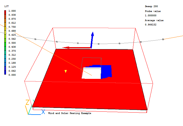
Un-averaged Contour of LIT at Z=5.368
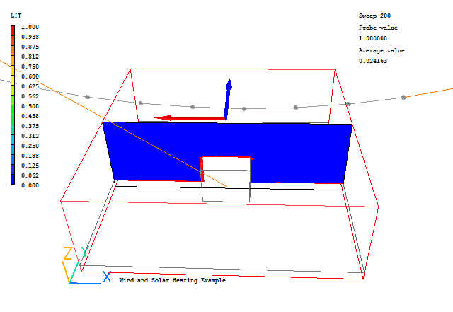
Un-averaged Contour of LIT at Y = 73.5995
The solar heat load can be checked by plotting contours of #QS2 (ensure that the ground plane is hidden or only showing its wire-frame):
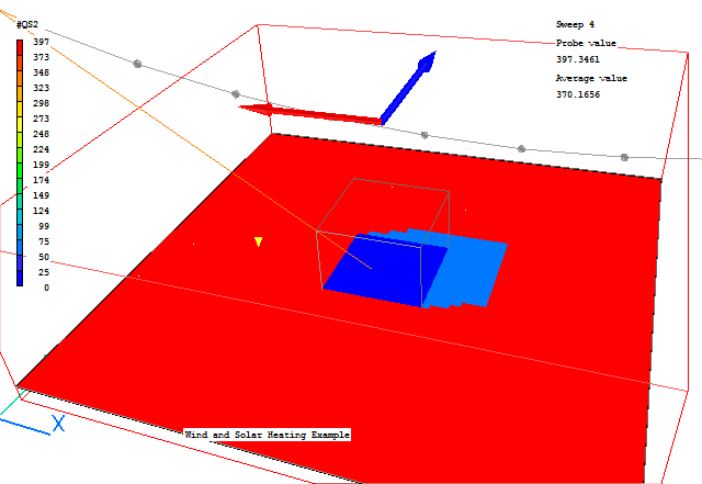
Un-averaged Contour of #QS2 at Z=4.73
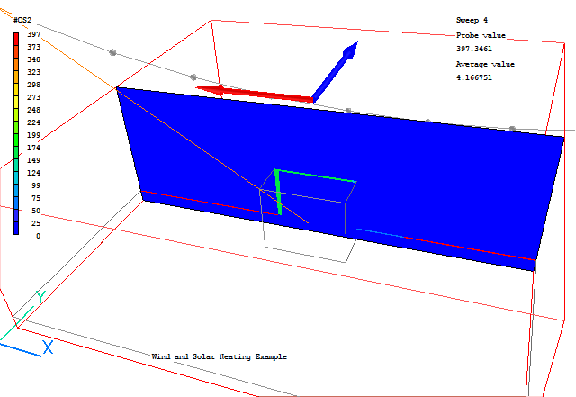
Un-averaged Contour of #QS2 at Y = 73.5995
From these images we can see that the shadow is behind the building as expected. In the shadow zone, only the diffuse heating is applied. The heat load is applied in the first layer of cells inside the solids.
The flow field outside the building should be like this (with contour averaging turned on):
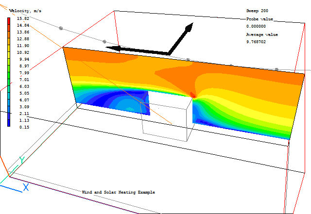
The temperature field (with contour averaging turned off) is like this:
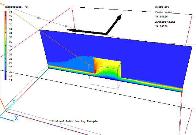
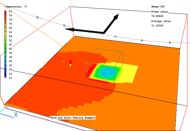
Qualitatively this is correct in that the sun-facing sides of the building are much hotter than the shadowed sides. However, the temperature level is far too high.
This is due to the choice of materials, and hence thermal conductivities. As was mentioned earlier for the building at least, all the properties should be some average of the materials composing the building.
We can check the sensitivity of the calculation by replacing the materials used with more conductive ones, and rerunning.
Before we change the settings, we can save the current results so that we can come back to them later without having to re-run the case.
In the PHOENICS-VR environment, click on 'Save as a case', make a new folder called 'WINDSUN', select the new folder, and save as 'RUN1'.
Return to the Editor. (Run, Pre-processor, VR-Editor).
Open the Object Management Dialog.
Double-click the SOIL object and open its Attributes dialog. Change the material to 111 Steel. Click OK twice to return to Object Management.
Double-click the BUILDING object and open its Attributes dialog. Change the material to 110 Silver. Click OK twice to return to Object Management.
We are only choosing these materials because they have much higher thermal conductivities, Silver being about 10 times that of steel, and steel 50 times that of brick. In steady state the density and specific heat do not matter. If the case were to be run in transient mode, then they would be crucial as they define the heat capacity of the solids.
In the PHOENICS-VR environment, click on 'Run', 'Solver'(Earth), and click on 'OK' to confirm running Earth.
In the PHOENICS-VR environment, click on 'Run', 'Post processor',then GUI Post processor (VR Viewer) Viewer)'. Click 'OK' on the file names dialog to accept the default files.
The temperature field now looks like this:
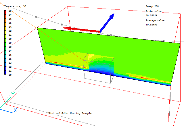
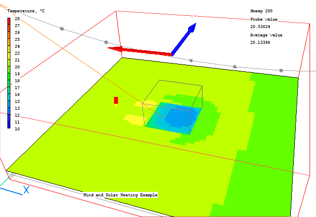
The sunny side of the building is still hotter, but the temperature is much lower. There is a small hot-spot in the lee of the building where the heat is not convected away so well.
In the PHOENICS-VR environment, click on 'Save as a case', , select the folder 'WINDSUN', and save as 'RUN2'.