The aim of this tutorial is to show:
The tutorial is in several stages. The first stage imports a single 3DS file for a complex building geometry. There is an obvious error in the imported file. In the second stage, this error is repaired and the detection of solids by the Earth solver is checked.
In the final stage, the single 3DS is split into separate files for each building. This would allow different material properties and / or sources to be applied to each building.
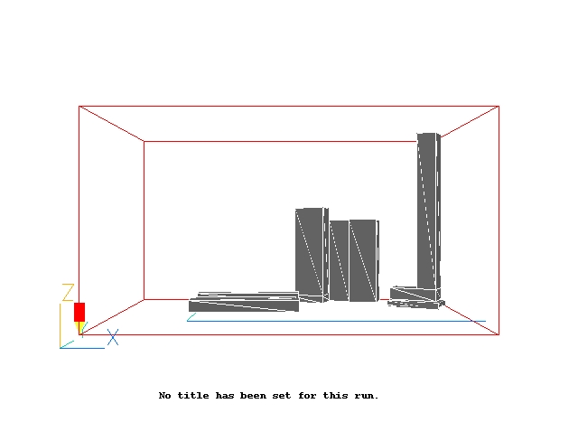
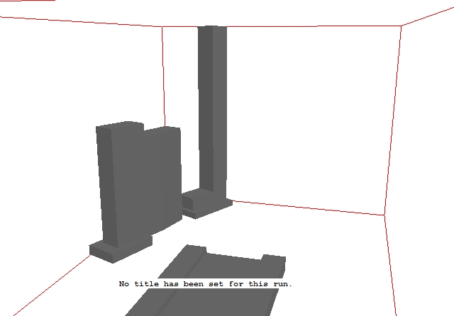
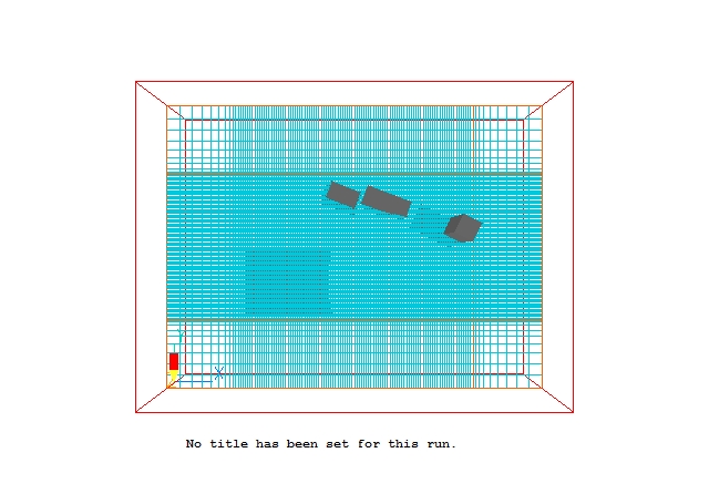
The full geometry of the case is shown in Figure 1 below.
Figure 1. The geometry of the CAD import example
The full CFD solution is not of interest for this tutorial.
A complete step-by-step guide, showing how to set the case from the default mode of operation, is provided below.
From the system level:
To enter the PHOENICS-VR environment, click on the PHOENICS icon on the desktop, or click on Start, programs, PHOENICS, PHOENICS.
From the commander level:
To enter the PHOENICS-VR environment, click on the 'Run vre' icon in the left column.
In PHOENICS-VR environment,
Start with an 'empty' case - click on 'File' then on 'Start New Case', then on 'Core'', then click on 'OK'; to confirm the resetting.
To enter VR Editor:
This is the default mode of operation.
Import the 3DS file
Click on
on the VR-Editor panel (or the O icon on the tool bar) to bring up the Object Management Dialog; and then on 'Object', 'New', 'Import CAD object'.
In the file browser, browse to \phoenics\d_polis\d_wkshp\cadimprt, and select the file cfd.3ds. Click 'Open'.
On the Import 3DS Data dialog that opens, click OK to accept the setting that the converted geometry file is to be placed in the current working directory. (If this were a common geometry that was to be used in many projects, it would be better to place it in the central store so that it was easily accessible). The following dialog should appear:
Sizing the geometry
Change the 'No' next to 'Take size from geometry file' to 'Yes'. On import, the size of the current object will be reset to that read from the geometry file.
Placing the geometry
By default, the imported object will be placed at the domain origin (or wherever the origin of the current object is set to). We want to leave 150m space around the buildings, so change the 'No' next to 'Take position from geometry file' to 'Yes'.
Click 'At object position' next to 'PHOENICS origin in CAD system'. It will change to 'User', and the Xorg, Yorg and Zorg boxes will be filled with the x0, y0 and z0 values shown on the dialog. These values act as an offset between the co-ordinates read in, and the co-ordinates in the Editor. (Xpos = Xpos CAD - Xorg). To move the buildings over by 150m, we reset Xorg to -458 and Yorg to -310. The dialog should now look like this:
Click OK. The converted geometry file will now be read in. The size of the new object will be set to 515.8m * 315.2m * 363.7m, at 150.0, 150.0, 0.0.
Click OK to close the Object specification dialog and OK to close the Object dialog.
On the toolbar, click the down arrow next to
and select 'Fit to window'. The screen should look like this:
Checking for Obvious Errors
Click on 'Domain' in the Object management Dialog, or click on the image background to release the highlighted object.
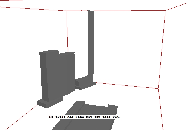
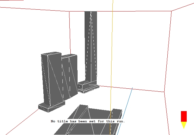
Using the mouse, rotate, pan and zoom the image to inspect the geometry. Details of the mouse operation are given in TR/326, VR-Editor Hand-Set, Mouse Control. You should be able to find this peculiarity:
The tall building at the back appears inside out whatever angle it is viewed from.
To help diagnose the problem, click 'View', 'Show backs of objects'. This tells VR-Editor to draw both sides of each facet, not just those facing outwards. The image should change to:
The inside-out part now looks correct. This is a good indication that the facets of the affected region are pointing in the wrong direction. Turn 'View','Show back of objects' off again.
Repairing the error
The Datmaker utility can be used to repair many common errors in geometry files. Click 'Settings', 'Datmaker operations'.
The Datmaker GUI should appear:
In the input box for 'Select first object', select B1. This is the object to be operated on.
As we have back-to-front facets, make sure 'Consistent' is ticked and 'Do Hole Mend' is not, then click OK to run Datmaker.
The repaired geometry will be called 'mygeom.dat', and a copy of the Q1 containing the model in its current (pre-repair) state will be saved to 'saved.q1'. Both these names can be changed if required. The saved q1 can be used to recover the model should something go very wrong with the repair.
If 'Post operation graphics display' is ticked, Datmaker will display the repaired geometry, but this is not usually required by users.
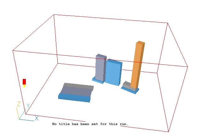
The screen should now look like:
To make sure that everything is correct, click 'View', 'Show back of objects' again to turn off double-sided facet drawing. The image should remain the same. Rotate the image to look at it from all directions, and check that there are no holes.
This should now not change when 'View', 'Show backs of objects' is turned on and off, indicating that all the facts do indeed point outwards.
Checking for Detection Problems
Having imported the geometry, it is worth checking to see if it will be detected properly by the Earth solver. Do do this, we need to set a mesh and perform 2 or 3 sweeps (iterations).
First make the domain size 150m bigger in X and Y and 50m bigger in Z. For a real calculation, the boundaries should be several times the height of the tallest building away from the buildings.
Click on the Mesh toggle
on the hand-set or toolbar, then click on the image to bring up the Grid mesh Settings dialog. Reset the Domain size to 815 in X, 615 in Y and 413 in Z.
Toggle all three directions from Auto to Manual. Click on 'Edit all regions in' 'X direction. Set the number of cells and powers in the three regions as:
Region Cells Power 1 10 -2 2 100 1 3 10 2 A positive power expands the grid from the start of the region towards the end, a negative power expands the grid from the end of a region towards the beginning. Click OK, then Edit all regions in Y and make the same settings. In Z, set 50 cells in region 1 with a power of 1, and 5 in region 2 with a power of 2. Click OK twice to close the dialogs. The grid should look like this:
Click on the Mesh toggle to turn off the mesh display.
Click on
on the hand-set or M on the toolbar to bring up the main Menu. Go to the Numerics page. Change the 'Total number of iterations' to 2, then Top Menu, OK to close the Main Menu.
Click 'Run' 'Solver' to make the Earth run.
Once the Solver run has finished, enter the VR-Viewer to examine the solution (Click 'Run' - 'Post processor' ,'GUI ').
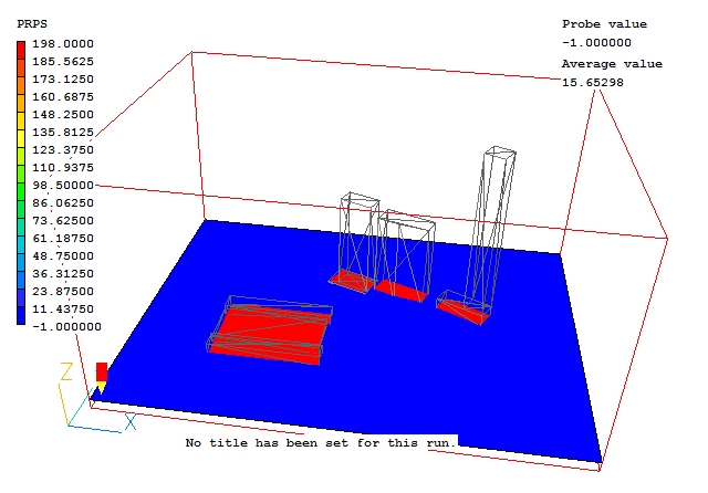
In the Viewer, switch the plotting plane to Z (click Z on the handset or toolbar), and select the property-marker variable PRPS by clicking the
icon on the hand-set or toolbar, then selecting PRPS from the list of variables. Switch the contours on by ticking 'Show contours' on the Viewer Options dialog, or by clicking
on the hand-set or toolbar. The PRPS contours should be blue in the airspace, and red inside the buildings.
To see inside the buildings, go to wireframe mode by clicking
on the hand-set or toolbar.
Moving the probe to around 18m, we can see that the buildings are detected well.
By moving the probe up and down in Z, and also scanning through the X and Y planes you can get a feel for how well the shapes have been picked up.
In the PHOENICS-VR environment, click on 'Save as a case', make a new folder called 'CAD', select the new folder, and save as '3DS'.
If still in the Viewer, return to the Editor by clicking Run - Preprocessor.
The splitting is also done by Datmaker. Click 'Settings', 'Datmaker operations'.
The Datmaker GUI should appear:
In the input box for 'Select first object', select B1. This is the object to be operated on.
Tick 'Object changes', and select 'Split'. As we have already repaired the back-to-front facets, un-tick 'Consistent' as we do not need to do it again. Click OK to run Datmaker.
The screen should now look like:
In the Object Management dialog we see that 10 new objects have been created, one for each closed volume in the original CAD file. The original blockage B1 has been turned into a NULL object, and the new blockages have been set to not affect the grid. This is to ensure that the mesh is not changed as a result of the splitting operation. Check this by turning the mesh display back on and having a look.
Switch the grid back to 'Auto', and then for each object activate 'Affects grid' 'In all directions' (this can be done from the 'Action' menu of the Object Management dialog, of from the right-click context menu for a selected object).
You can go back to the grid settings for each direction and investigate how changes to the auto-mesh parameters affect the grid.