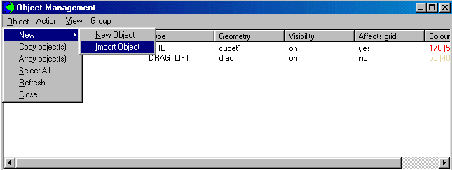

Such objects have been characterised by:
When a user has completed the introduction of data, and quitted the interactive session, the results of his settings are recorded in the Q1 file.
A typical example appears in Input-Library case v100
The VR-Editor provides no way of extracting an object from an earlier-written Q1 file and bringing it into the current 'VR world'; and, even if it did, Q1 files are too case-specific to be convenient places to store re-usable-object information.
A user who is skilled in the art of editing VR-type Q1s could, in principle, use a word-processor to transfer blocks of information from one Q1 to another, prior to the new VR session.
However, such users are few; and CHAM has done nothing to encourage their activities.
The practice is especially useful when the objects are characterised, in practice, by rather few parameters, which may well remain the same from case to case, such as:
The reasons for the tendency and its lessening are as follows:
Thus, if a solid rectangular grid-fitting object was to be represented, one initial-value patch would be used so as to specify the material index (i.e. PRPS value) of each cell within the block.
Then six additional 'wall-type' patches would be created, one for each surface, to express the frictional influence of those surfaces on the flow.
This practice has been unnecessary for many years; for the 'EGWF' (i.e. earth-generated-wall-function) feature enables the frictional influence to be deduced simply from knowledge of which cells contain fluid and which solid.
Thus the initial-value patch specifying the material appeared in Group 11 of the Q1 file, whereas the heat source would appear in Group 13.
The distinction between initial-condition and boundary-condition (i.e. group 11 and group 13) patches must have seemed like 'a good idea at the time'; but the distinction is artificial; and it needed not be perpetuated.
Section 2: The POB file
Changes of thinking are assisted by changes of nomenclature.
Therefore the
'Phoenics Object file', with the extension .pob, has
been introduced.
Unlike the more familiar .dat file, it may also contain information of a
non-geometric character.
Although in fact .dat and .pob files are treated in the same way by the PHOENICS satellite, the former name is preferred for the old-style geometry-only files (of which there are very many); while the latter is used for any file which also contains non-geometric attributes.
A PHOENICS Object File may contain data regarding a single object; or it may describe several objects which are linked together as an 'assembly'
> OBJ,    POSITION,    5.000000E-01, 4.500000E-01, 4.500000E-01
> OBJ,    SIZE,        0.000000E+00, 1.000000E-01, 1.000000E-01
> OBJ,    GEOMETRY,    default
> OBJ,    ROTATION24,        1
> OBJ,    TYPE,        FAN
> OBJ,    VELOCITY,     1.234000E+00, 0.000000E+00, 0.000000E+00
> OBJ,    TEMPERATURE,  0.000000E+00
> OBJ,    PRESSURE,     0.000000E+00
> OBJ,    TURB-INTENS,  5.000000E+00
Evidently it comprises merely a set of lines such as are printed by the PHOENICS VR-Editor in the Q1 file.
The POB file for several objects is used to save a number of objects which go together to make up a component, which it is desired to use in more than one model.
It starts with an ASSEMBLY object which defines the overall size and location, and then contains the definitions of all the component objects.
The following example is of a FAN object with an adjoining domain-fluid blockage having a heat source. This would represent a fan-plus-heater unit.
! Start information about master object: FANHEAT
!--------------------------------------------------
!
> OBJ,    POSITION,    5.000000E-01, 4.500000E-01, 4.500000E-01
> OBJ,    SIZE,        5.000000E-02, 1.000000E-01, 1.000000E-01
> OBJ,    GEOMETRY,    cubet1
> OBJ,    ROTATION24,        1
> OBJ,    TYPE,        ASSEMBLY
!
! Start information about individual components: FAN
!-----------------------------------------------------
!
> OBJ,    POSITION,    5.000000E-01, 4.500000E-01, 4.500000E-01
> OBJ,    SIZE,        0.000000E+00, 1.000000E-01, 1.000000E-01
> OBJ,    GEOMETRY,    cube2t
> OBJ,    ROTATION24,        1
> OBJ,    TYPE,        FAN
> OBJ,    VELOCITY,     1.234000E+00, 0.000000E+00, 0.000000E+00
> OBJ,    TEMPERATURE,  0.000000E+00
> OBJ,    PRESSURE,     0.000000E+00
> OBJ,    TURB-INTENS,  5.000000E+00
!
! Start information about individual components: HEAT
!-----------------------------------------------------
!
> OBJ,    POSITION,    5.000000E-01, 4.500000E-01, 4.500000E-01
> OBJ,    SIZE,        5.000000E-02, 1.000000E-01, 1.000000E-01
> OBJ,    GEOMETRY,    cubet1
> OBJ,    ROTATION24,        1
> OBJ,    TYPE,        BLOCKAGE
> OBJ,    MATERIAL,    DOMAIN
> OBJ,    HEAT_FLUX,    0.000000E+00, 5.000000E+03
The position coordinates of the individual components are defined as
relative to those of the master.
When the master is moved or re-sized, all the components are moved or scaled
accordingly.
The '! Start information...' lines are crucial, as they tell the Editor when the definition of the next component starts.
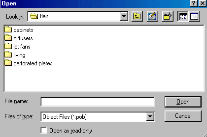
POB files can be read from either the current working directory, or from any subdirectory of /phoenics/d_satell/d_object/public.
See also the
TR326 entry on ASSEMBLY objects, which use the POB file to save the
components of an assembly,
and also the tutorial
Working with ASSEMBLY Objects.
The .pob file is not the first to contain both geometric and non-geometric information; for the .geo file produced by the Shapemaker modules did the same.
Moreover, whereas the VR-Editor could work only with imported shapes, Shapemaker could create them AND assign attributes to the associated objects.
In order to simplify the user's task, the capabilities of both the VR-Editor and Shapemaker have been combined, so that:-
Section 3. POBs for heating and ventilating
PHOENICS provides a library of HVAC-related POB files, namely:


POB files can be created using either The Shapemaker program or the VR-Editor.
The VR-Editor can also import or export assemblies of objects in a single POB file. The information stored in a POB file may include:
One such way is the use of the long-existing PIL INCL statement.
Thus,
if a file called, say, v100obs.htm were to be created which contained
the statements regarding the objects of case v100, revealed above
by clicking
here,
then those
statements could be replaced in the q1 file by the single line:
INCL(v100obs.htm).
The satellite will react to this q1 in precisely the same way as it does to the original one, in the sense that the q1ear and eardat files which it produced would be identical.
Moreover, if the lines referring to the domain were similarly transferred to v100obs.htm, namely:
 GVIEW(P,7.390102E-01,-6.736943E-01,0.000000E+00)
 GVIEW(UP,0.000000E+00,0.000000E+00,1.000000E+00)

> DOM,    SIZE,        1.000000E+01, 2.000000E+00, 1.000000E+00
> DOM,    MONIT,       5.000000E-01, 1.000000E+00, 5.000000E-01
> DOM,    SCALE,       1.000000E+00, 1.000000E+00, 1.000000E+00
> DOM,    SNAPSIZE,    1.000000E-02
> DOM,    RELAX,       5.000000E-01
the result would also have been the same.
Of course, if the satellite is operated in the interactive mode, the Q1 which it saved will be different from the one which it read; for the > DOM .... and > OBJ .... lines would have reappeared in it.
> DOM, SIZE, 1.000000E+01, 2.000000E+00, 1.000000E+00by:
XULAST=1.000000E+01; YVLAST=2.000000E+00; ZWLAST=1.000000E+00
> DOM,    SIZE,        XULAST,YVLAST,ZWLAST
for the q1ear, eardat ( and, in interactive mode, q1 ) files would remain identical.
Similarly, it would be permissible to declare, set and use new variables, for example:
Real(xdom,ydom,zdom)
xdom=10.;ydom=2.;zdom=1.
> dom,size,xdom,ydom,zdom
Once again, the result would be identical.
Why is this important? Because it provides a way to protect user-provided settings from the forgetfulness of the VR-Editor.
If the above settings had been placed in the q1 file itself, they would not have appeared in the q1 written by the VR-Editor; in effect, they would have been wiped out.
However, the Editor has no influence on v100obs.htm, which remains intact.
Having recognised that any PIL statements can be both used and preserved, let us go further, by re-writing the v100obs.htm as follows:
array(nam,3) ! for the names of the three objects
array(pos.3.3) ! for the x,y,and,z coordinates of the three objects
array(size.3.3)  ! for the x,y,and,z sizes of the three objects
followed by:
nam(1)=B1
pos(1,1) =0.0E+00; pos(1,2) = 0.0E+00; pos(1,3) = 0.0E+00
size(1,1)=0.0E+00; size(1,2)= 2.0E+00; size(1,3)= 1.0E+00
pos(2,1) =5.0E+00; pos(2,2) = 0.0E+00; pos(2,3) = 0.0E+00
size(2,1)=0.0E+00; size(2,2)= 2.0E+00; size(2,3)= 1.0E+00
pos(3,1) =1.0E+01; pos(3,2) = 0.0E+00; pos(3,3) = 0.0E+00
size(3,1)=0.0E+00; size(3,2)= 2.0E+00; size(3,3)= 1.0E+00

> OBJ1,   NAME,        B1
> OBJ1,   POSITION,    pos(1,1) , pos(1,2) , pos(1,3)
> OBJ1,   SIZE,        size(1,1), size(1,2), size(1,3)
> OBJ1,   CLIPART,     cube3t
> OBJ1,   ROTATION24,        1
> OBJ1,   TYPE,        INLET
> OBJ1,   PRESSURE,      0.000000E+00
> OBJ1,   VELOCITY,      1.800000E+01, 0.000000E+00, 0.000000E+00
> OBJ1,   TEMPERATURE,   0.000000E+00

> OBJ2,   NAME,        B2
> OBJ2,   POSITION,    pos(2,1) , pos(2,2) , pos(2,3)
> OBJ2,   SIZE,        size(2,1), size(2,2), size(2,3)
> OBJ2,   CLIPART,     cube11
> OBJ2,   ROTATION24,        1
> OBJ2,   TYPE,        PLATE
> OBJ2,   POROSITY,      1.500000E-01
> OBJ2,   RESISTANCE,    4.000000E-01
> OBJ2,   SIDE,        BOTH

> OBJ3,   NAME,        B3
> OBJ3,   POSITION,    pos(3,1) , pos(3,2) , pos(3,3)
> OBJ3,   SIZE,        size(3,1), size(3,2), ,size(3,3)
> OBJ3,   CLIPART,     cube12t
> OBJ3,   ROTATION24,        1
> OBJ3,   TYPE,        OUTLET
> OBJ3,   PRESSURE,      0.000000E+00
> OBJ3,   TEMPERATURE,  -1.026000E+04
> OBJ3,   COEFFICIENT,   1.000000E+03

However, the arrays used there are not strictly needed; and a more compact representation of the same data is provided by i201obsb.htm
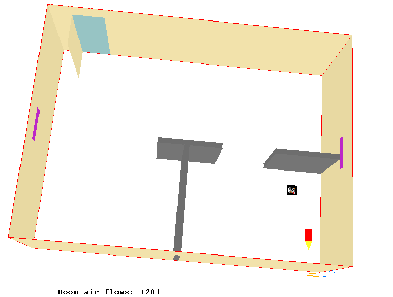
Inspection of that file permits the following conclusions to be drawn:
> OBJ,    NAME,        wall-l2
> OBJ,    POSITION,    0.0, suppypos+suppwide, 0.0
> OBJ,    SIZE,        roomhigh, roomwide-suppwide-suppypos,0.0
which describe the part of the 'low' wall which lies immediately beneath the air-supply aperture.
> OBJ,infsrc_tem1, :fireflux: with if(tem1.lt.2000)has been inserted so as to reflect the fact that heat generation ceases when the temperature rises to the adiabatic combustion temperature (here estimated to be 2000 degrees) because the fuel and oxygen become depleted locally.
The satellite reads the line, dutifully transmits the information via a SPEDAT line to the solver, and, if it is working in the 'silent' mode, lets line incl(i201obsb.htm) remain in the q1 file.
If it is working in interactive mode, it will write the numerical implications of the i201obs.htm into the q1 file instead of the incl statement; but the i201obs.htm file itself will remain intact.