Click for contents list.
This document describes changes made between PHOENICS version 3.6.1 and 2006. The much greater changes between PHOENICS 3.5 and 3.6.0 and 3.6.1 are described in an earlier version of this document, here.
Changes Common to VR Editor and VR Viewer


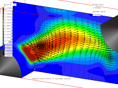
The inflow can be specified as Cartesian velocity components (as above), velocity normal to the blockage surface (as below), or as volume or mass flow rate.
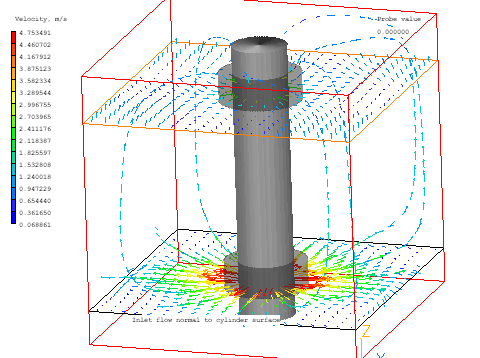
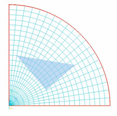
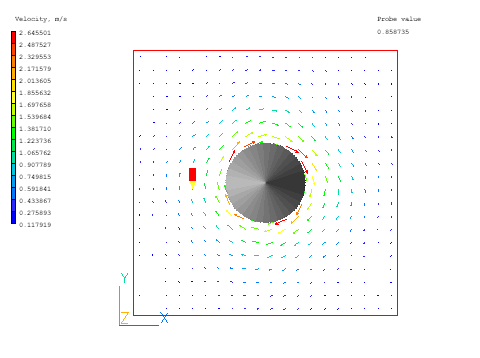
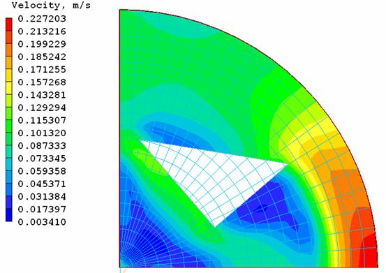
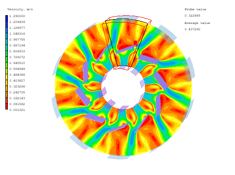
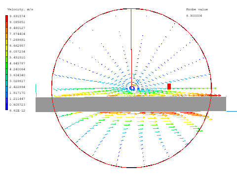
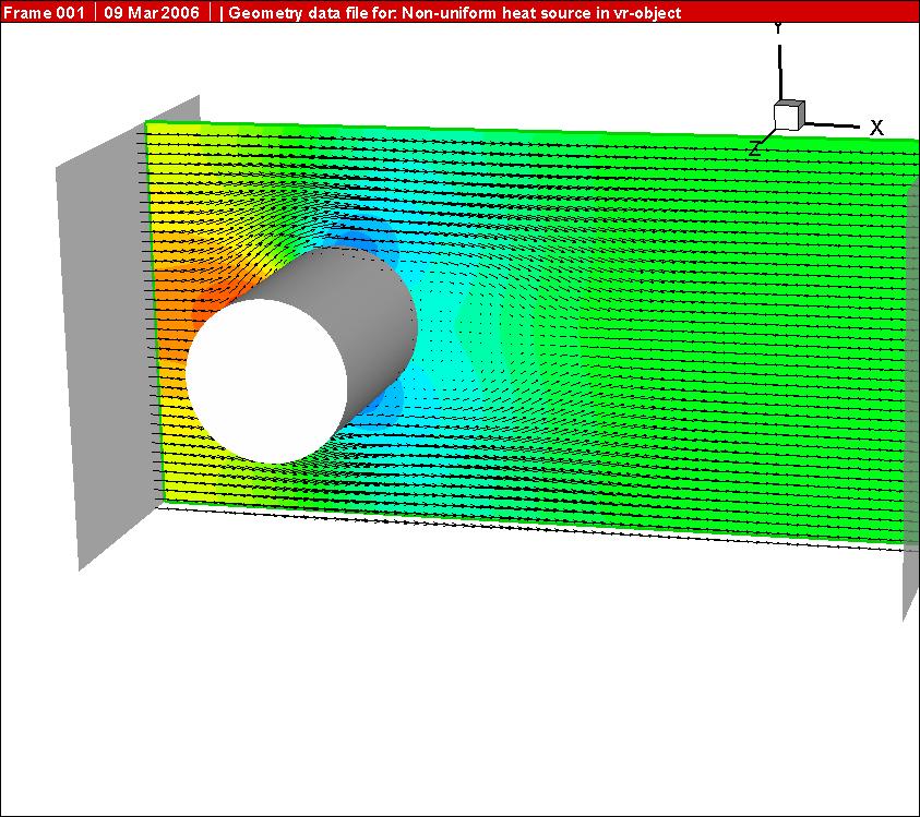
In Polar, the slide velocity can be in m/s or rad/s. The following image shows a bar being pulled at constant speed through a Polar domain:
An 'auto' function has been introduced which switches between the stable and unstable forms depending on the local flow direction. This should produce better results for cases with zones of both stable and unstable stratification.
The 'auto' option is now the default for new cases set via the Editor, but constant values can still be set from the Main Menu - Sources panel.
The domain-partitioning technique is useful for computer simulation of flow phenomena characterised by a predominant direction of flow, as for example when several chemical-plant vessels are connected in series, as sketched below, the flow being always from left to right.
     ---------------        ---------------        -------------
     |             |        |              |       |           |
     |             |        |              |       |           |
     -   vessel 1  ----------  vessel 2    ---------  vessel 3 ---------
     -             ----------              ---------           ---------
     |             |        |              |       |           |
     |             |        |              |       |           |
     ---------------        ---------------        -------------
        upstream  >>>>>>> direction of flow >>>>>>>>  downstream
It is of course possible, with sufficient computer memory, to simulate all three vessels, and the pipes and spaces between them, at the same time; but it is seldom either necessary or cost-effective to do so; for there is usually no significant influence of happenings in downstream vessels on those in upstream ones.
A similar situation arises when it is necessary to simulate the flow over an extensive tract of terrain, for example a complete city or a wide forest. Partitioning is then possible because usually the direction of wind varies little from place to place.
Thus, if the wind blows predominantly from the north west over the area of land indicated below, the sub-areas marked 1, 2, 3, etc below can be simulated separately but in sequence, if the output from an earlier calculation is stored for use as input to a later one.
                      North
      |----------|---------|---------|---------|--------|--------|---
      |          |         |         |         |        |        |
      |    1     |   2     |   3     |    4    |   5    |   6    |
  West|          |         |         |         |        |        |
      |          |         |         |         |        |        |
      |----------|---------|---------|---------|--------|--------|---
      |          |         |         |         |        |        |
      |    7     |   8     |   9     |    10   |   11   |   12   |
      |          |         |         |         |        |        |
      |          |         |         |         |        |        |
      |----------|---------|---------|---------|--------|--------|---
      |          |         |         |         |        |        |
      |    13    |   14    |   15    |    16   |   17   |   18   |
      |          |         |         |         |        |        |
      |          |         |         |         |        |        |
      |----------|---------|---------|---------|--------|--------|---
When it is desired to take account in the simulation of the shapes of individual buildings in the city, or of fire-breaks traversing the forest, the computer-memory requirements could not be met by commonly-available machines if the whole region were to be simulated at once.
The domain-partitioning technique however does permit the simulation to be performed by computers of modest size, by splitting the whole terrain into parts which are sufficiently small to be handled by the available computer; and it then causes the parts to be simulated one after the other, the upwind ones being considered first.
At the end of each calculation, data describing the flow conditions on the downstream boundaries are placed into files which serve as 'transfer objects'; for the data can then be imported as upstream-boundary data for the later-to-be simulated next-downstream part.
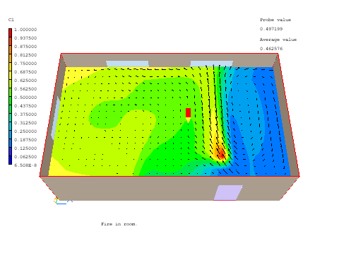
The first image shows the smoke distribution in a room with a fire. The open windows are treated as 'export' objects.
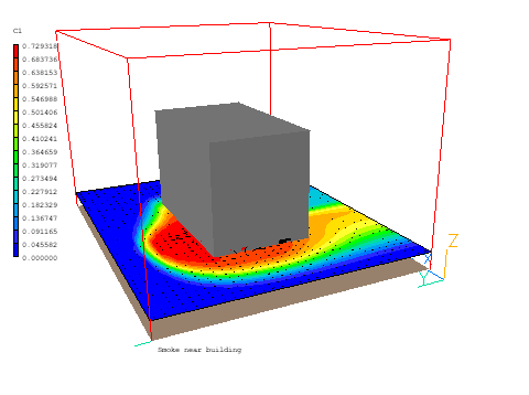
The next image shows the flow around the outside of the building the room is in. The building itself is a blockage. The flow from the windows, saved in the first run, is now used as the inlet condition via 'import' objects. Around the corner from the first room is a second room with open windows, set as outlets. The flow through them is saved via 'export' objects.
The final image shows the flow in the second room, which uses the saved window mass-flows from the second run.
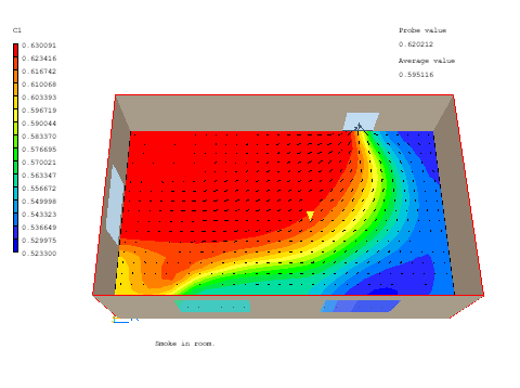
It has this been possible to calculate the three parts separately with grids suitable for each part whilst maintaining the linkage between them.
