
In order to facilitate the use of the new capabilities developed for PHOENICS 3.6, the graphical user interface has introduced many corresponding new features which allow the user to invoke the new functions or set input parameters as described below. Existing features have also been improved to make the graphical interface easier to use.
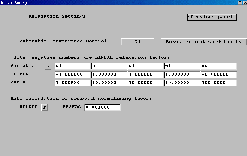
Automatic convergence control is set as the default option as described in Chapter 2. The panel also allows the user to set a maximum increment for each variable.
Several changes have occurred within the main graphics window:
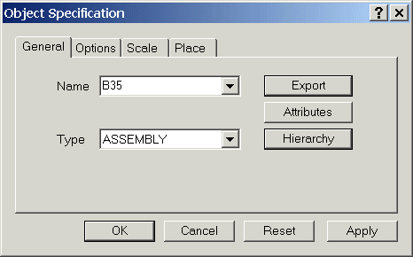
Object dialog replaced by Object Management Panel and tabbed Object Specification dialog
The old 'Object' button and other buttons on the Main control panel have been replaced by the new Object Management dialog. The design and layout of the window-based Object Management is more rational and logical than the old Fortran panels.
Any column can be sorted in ascending order and a right-click will bring up a context-dialog as shown in the figure below.
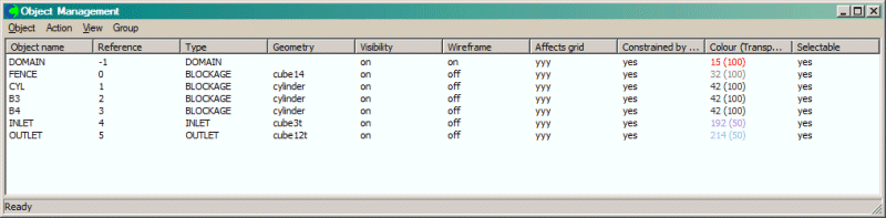
The order of objects in the Q1 can be changed by right-clicking on the 'Reference' column. This brings up a context menu from which the objects can be re-ordered.
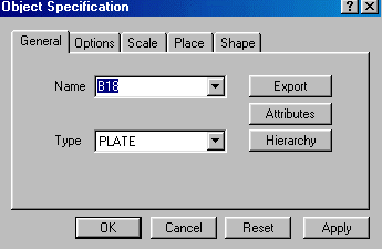
The 'New object' dialog has become a tabbed dialog, with the various options grouped onto individual panes.
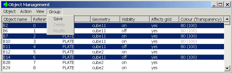
Group handling facility
A Group handling facility has been made available within the Object Management dialog. It is invoked automatically if more than one object is selected. The dialog allows standard Windows multiple selection using "shift" and "control" keys. While the Object Management dialog is open, multiple selection may also be achieved by holding the "control" key down while selecting an object in the main graphics window.
All selected objects can be moved together, have their colour and transparency set, or be revealed or hidden.
The group can be duplicated or arrayed, moved, deleted, saved and retrieved. All object geometries, types and attributes will also be preserved.
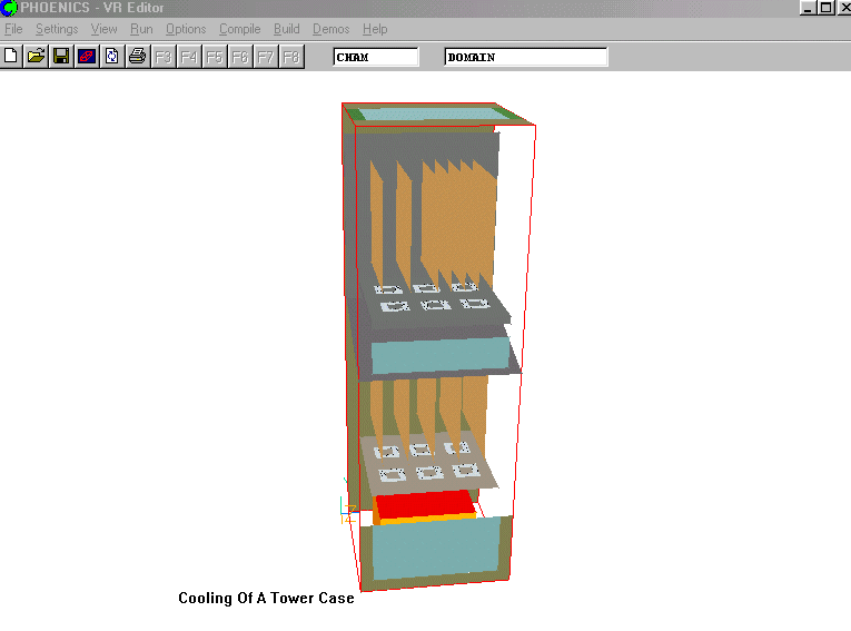
The multiple group facility can be effectively used to create the model of a telephone exchange tower case shown in the following figure, where many fans and PCBs can be grouped and arrayed.
Multiple Groups can be saved and read from the Q1.
Propagation of Attribute Changes
Changes made to the attributes for a member of a group are (optionally) propagated through the remainder of the group.
Link to Shapemaker directly from Object Specification dialog as described in Chapter 8.
The following new types of object have been added to the existing list of object types:
Objects can be added to or removed from a assembly object through the Hierarchy dialog.
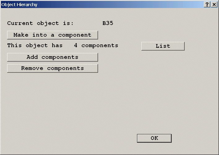
All size and position changes made to the assembly object are also applied to all the components, and all the objects in the assembly can then be exported to a POB single file. The saved assembly objects can then be imported into another model.
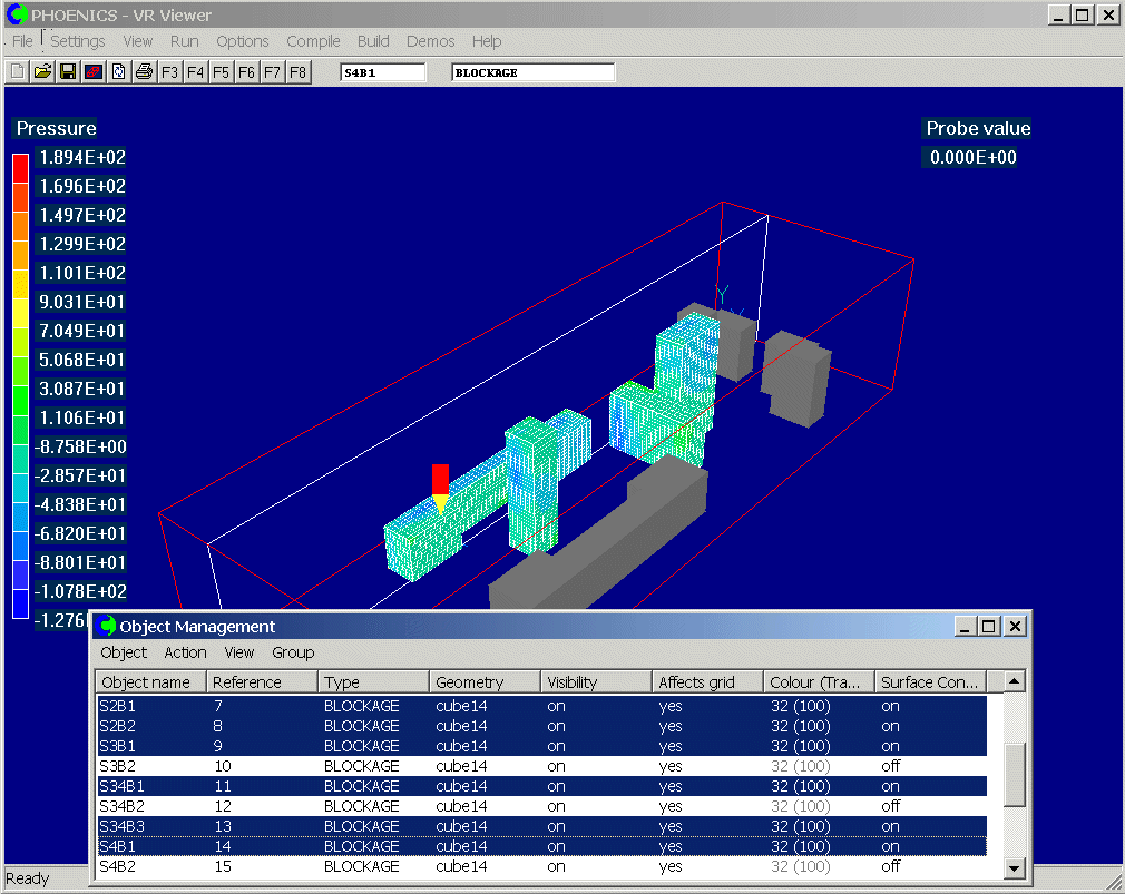
The Object Management Panel is also present in the VR-Viewer.
It can turn the surface contouring On or Off for the selected objects, and display the nett sources and pressure loadings.
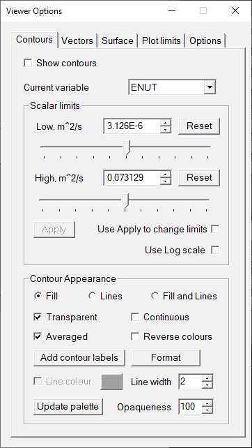
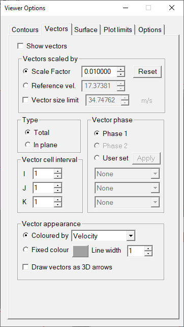
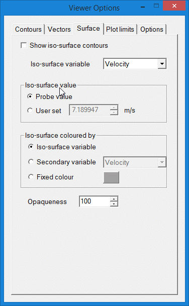
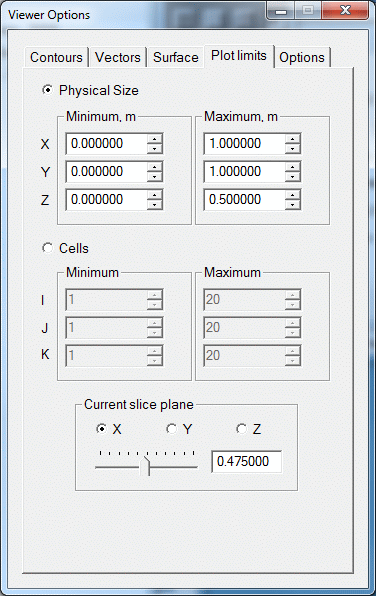
The control dialogs for Contours, Vectors, Iso-surface and Plot limits have been made into a single tabbed dialog.
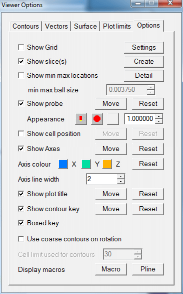
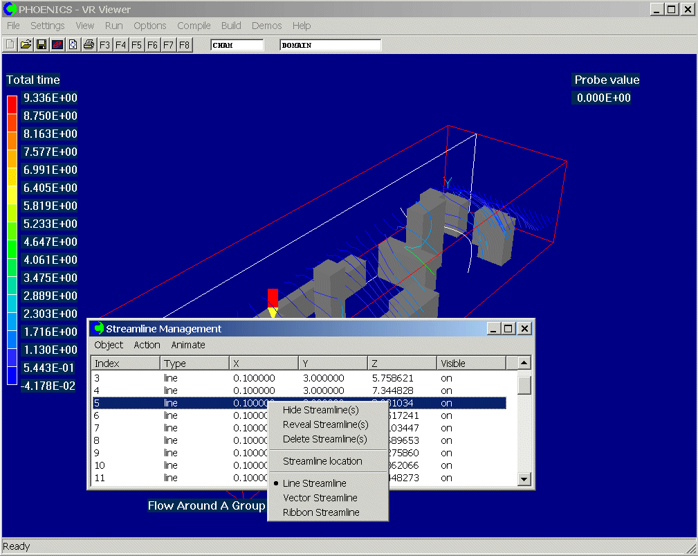
Streamline and Slice Management Panels are similar to object management. Through the streamline management panel, it becomes a simple matter to switch individual streamlines or groups of streamlines on or off.
The location of individual streamlines can also be adjusted to get the desired images.
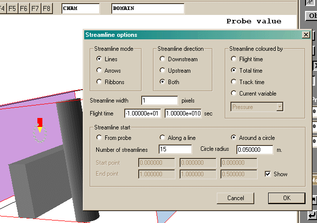
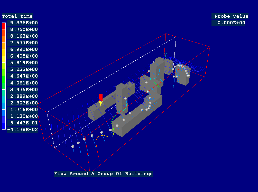
The streamline options dialog has also been redesigned, so that all the options are immediately visible. While the options dialog is open small grey balls are displayed to indicate the current starting locations for any streamlines. For example, in the figure below, streamlines will be generated in a circle around the probe.
Animation of streamlines using moving balls, moving vectors or moving line segments.
Several options are given for defining the streamline animation including the number of frames to be used, and number of balls or vectors along the streamline. The animation may also be saved as an animated GIF file or an AVI file.
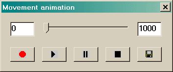
The 'Record animation' button on the handset, ![]() , brings up a recording dialog:
, brings up a recording dialog:
This allows a sequence of rotations, probe movements with the associated contours, vectors and iso-surfaces to be captured to an animated GIF or AVI file.