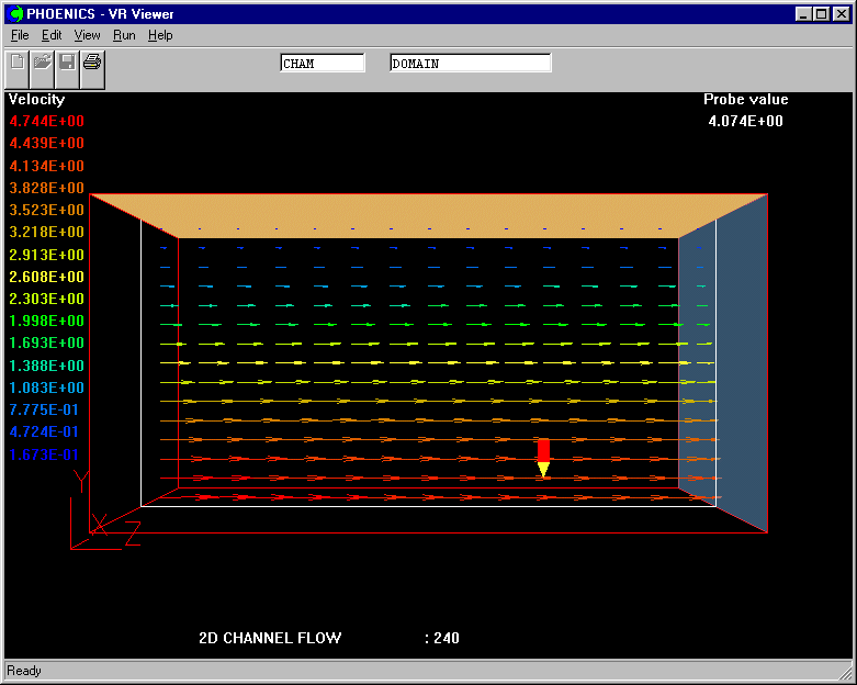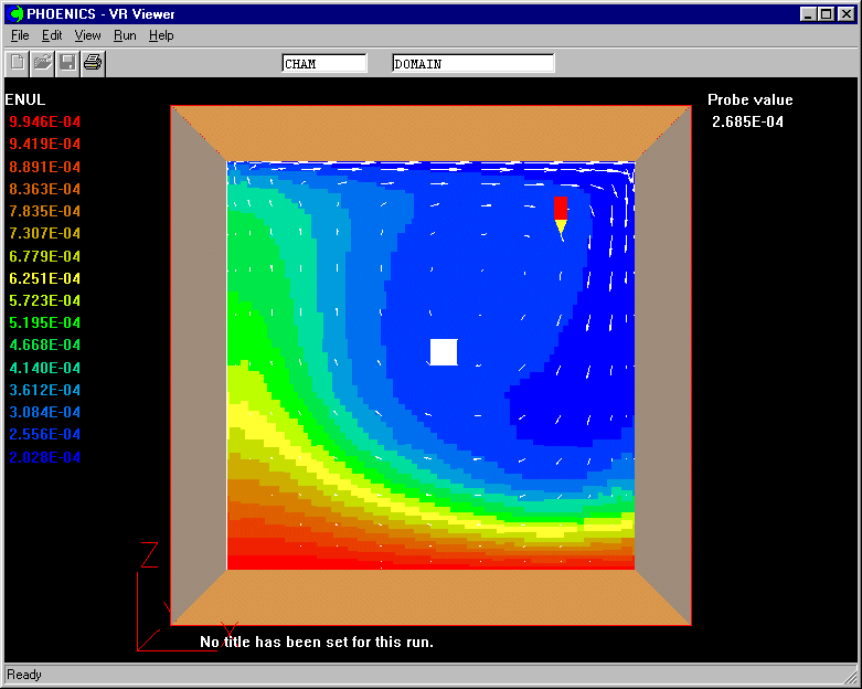
There follow two workshop sessions which create PLANT settings for:-
Workshop 1 - Non-linear PropertiesThis case analyses the flow in a cavity, the top wall of which moves with a constant velocity. The top wall is at one temperature, the moving wall is at a different temperature and two other walls are adiabatic. The calculation is made for the Reynolds number Re = 100 , for Prandtl number Pr = 1 and for the exponent in the viscosity formula EMU = EMU0*EXP(-beta.(T - T0)).
In this case, EMU0 = 1E-3, beta=1.6 and T0 = 0.0.
( See M. Morzynski and Cz. O. Popiel in Numerical Heat Transfer, v.13, pp. 265-273, 1988 for further details and comparison).
Accessing PHOENICS-VR.
From the system level:
To enter the PHOENICS-VR environment, click on the PHOENICS icon on the desktop, or click on Start, programs, PHOENICS, PHOENICS.
From the commander level:
To enter the PHOENICS-VR environment, click on the 'Run vre' icon in the left column.
In PHOENICS-VR environment,
Start with an 'empty' case - click on 'File' then on 'Start New Case', then on 'Core', then click on 'OK'; to confirm the resetting.
To enter VR Editor:
This is the default mode of operation.
Set the domain size and activate solution of the required variables:
Click on 'Main Menu' and set 'Non-linear properties using PLANT' as the Title
Click on 'Geometry'. Set the domain size to 0.1 * 0.1 * 0.1.
Click 'OK' to close the Grid mesh dialog.
Click on 'Models'.
Leave the 'solution for velocities and pressure' ON.
Set the Energy Equation to TEMPERATURE.
Click on 'Turbulence models' and select 'Laminar'.
Click on 'Properties'
Click on 'Property Storage'.
Turn the storage of Viscosity ON, so that it can be plotted after solution has been obtained.
Click on 'Previous panel'
Click on 'Edit properties of current material'.
Click on 'Conductivity', and select 'CONST Prandtl-No'/'OK'.
Set the Prandtl Number to 1.0.
Click on 'Previous panel', 'Top menu', and on 'OK' to exit the Main Menu.
Click on 'Reset' button and then 'Fit to wondow'/'OK'.
Create upper, moving wall:
Click on 'Settings', 'New' and 'New Object'.
Change name to MOVING.
Click on 'Size' and set Size of the object as:
Xsize: 0.1
Ysize: 0.1
Zsize: 0.0
Click on 'Place' and set Position of the object as:
Xpos: 0.0
Ypos: 0.0
Zpos: 0.1
Click on 'General'.
Select 'Type' as Plate.
Click on 'Attributes'.
Set the Slide Velocity to 1.0 in the X direction.
Click on 'Energy Source - Adiabatic'. Select Surface temperature and set the surface temperature to 1.0.
Click on 'OK' to close the attributes dialog box.
Click on 'OK' to close the Object Specification Dialogue Box.
Create the lower stationary wall by duplicating MOVING:
Click on the 'Duplicate object or group' button on the handset and then click on 'OK' to confirm duplicating.
Double click on the image of the copy. This bring up the Object Specification Dialogue Box of the object copy.
Change name to FIXED.
Click on 'Attributes'. Set the Slide Velocity to 0.0 in the X direction.
Set the surface temperature to 0.0. Click on 'OK' to close the attributes dialog box.
Click on 'Place' and change Zpos to 0.0
Click on 'OK' to exit from the Object Dialogue Box.
Create the right adiabatic wall:
Click on 'Settings', 'New' and 'New Object'.
Change name to RIGHT.
Click on 'Size' and set Size of the object as:
Xsize: 0.0
Ysize: 0.1
Zsize: 0.1
Click on 'Place' and set Position of the object as:
Xpos: 0.1
Ypos: 0.0
Zpos: 0.0
Click on 'General'.
Define Type as Plate.
Click on 'OK' to exit from the Object Dialogue Box.
Create the left adiabatic wall by duplicating RIGHT:
Click on the 'Duplicate object or group' button and then click on 'OK' to confirm duplicating.
Double click on the image of the copy to bring up the Object specification dialog box.
Change name to LEFT.
Click on 'Place' and change Xpos to 0.0.
Click on 'OK' to exit from the Object Dialogue Box.
Create a fixed-pressure point in the middle:
Click on 'Settings', 'New' and 'New Object'.
Change name to FIXEDP.
Click on 'Size' and set Size of the object as:
Xsize: 0.005
Ysize: 0.1
Zsize: 0.005
Click on 'Place' and set Position of the object as:
Xpos: 0.05
Ypos: 0.0
Zpos: 0.05
Click on 'General'.
Define Type as Pressure_Relief.
Click on 'OK' to exit from the Object Dialogue Box.
Set the grid:
Click on the 'Mesh toggle' button. The default mesh (shown as orange lines) will appear on the screen.
Click anywhere on the image, and the 'Grid mesh settings' dialog box will appear.
Change the Number of cells to 15 in X and 15 in Z.
Set Power/ratio for both X and Z to 2.0, and Symmetric to Yes.
Click on 'OK'; to close the dialog box. The mesh will now be shown as blue lines.
Click on 'Mesh toggle' again to turn off the mesh display.
Make the PLANT settings:
Click on 'Run', 'Pre processor' then 'Fortran creator (Plant menu)'.
Click on 'Properties of the medium', then click 'Add'.
On the next panel, scroll the list of available properties down until 'laminar kinematic viscosity' appears. Then click on it to select it.
In the 'PLANT statements' box, enter the formula:
VISL=1.E-3*EXP(-1.6*TEM1)
Click OK to set the expression, then Exit to quit the PLANT menu.
Make the solution control settings:
Click on 'Main menu', then on 'Numerics'.
Leave the total number of iterations to 100.
Click on 'Relaxation'.
Switch 'Automatic convergence control' OFF
Set the Self-Adjusting Relaxation algoritHm (SARAH) parameter to 0.005
Set the relaxation value for TEM1 to 1000.
Click on 'Previous panel', 'Top menu' and 'OK' to exit the Main menu.
In the PHOENICS-VR environment, click on 'Options', then 'Run version'. For Earth, select 'Private'.
Click on 'Run', 'Solver' (Earth)'.
Click on 'OK' to confirm running the Solver.
Click on 'Yes' to allow the compilation and re-linking to proceed.
In the PHOENICS-VR environment, click on 'Run', 'Post processor',then GUI Post processor (VR Viewer) Viewer)' and view the velocity vectors, contours and isosurfaces. Click on C to select the viscosity variable, ENUL. (Hint - change the slice direction to Y)

Workshop 2 - linear inlet profile
This workshop shows the user how to set a linear inlet velocity profile using PLANT. It is based in library case 240. The library case is 2 dimensional in the Y-Z plane, with Z as the main flow direction. The inlet velocity is uniform at 5.0, and the inlet enthalpy is 9.0.
The inlet mass-flow will be calculated from:
Min = 5.0*RHO1 *(YVLAST-YG2D))
and the inlet velocity from:
Win = 5.0*(YVLAST-YG2D)
The inlet enthalpy will be constant at 9.0.
Here, YVLAST is the domain height, and YG2D is the index of the store containing cell-centre locations in the Y direction.
Accessing PHOENICS-VR.
From the system level:
To enter the PHOENICS-VR environment, click on the PHOENICS icon on the desktop, or click on Start, programs, PHOENICS, PHOENICS.
In PHOENICS-VR environment,
Load library case 240 - click on 'File' then on 'Load from Libraries'. Enter 240 in the case number box, then click on 'OK'; to confirm the loading.
Click on 'Satellite command prompt' and press 'return' key until the geometry appears on the screen. You may now close the Satellite command prompt.
De-activate the INLET object - it will be replaced by PLANT coding.
Click on 'Object management' button on the hand set
Double click on the IN object from the list. This brings up the object specification dialog box.
Click on 'attributes'.
Change 'Type' from INLET to 'NULL'. Click 'OK' to close the Object specification dialog box.
The inlet object will be replaced by a null object. The idea is to preserve the grid, but eliminate any onther effect of the original object.
Reset the Outlet Coefficient
Click twice on the OUTLET object from the list on the object managemnet dialog box.
Click on 'Attributes'. Change the Coefficient from 1.0 to 1000. This will keep the exit pressure closer to zero.
Click 'OK' twice to close the object specification dialog box.
Refine the grid.
Click on 'Mesh toggle' on the hand set, then anywhere on the domain.
Change the number of cells in Y and Z from 5 to 15. Click 'Ok' to close the mesh dialog, and 'Mesh toggle' again to hide the grid display.
Modify the numerical controls
Click on 'Main menu', then 'Numerics'.
Reset the total number of iterations to 200.
Click on 'Relaxation', and set the Self-Adjusting Relaxation algoritHm (SARAH) parameter to 0.005.
Activate graphical monitoring of convergence
Click on 'Previous panel', then 'Output'.
Toggle the Monitor display mode from 'ASCII' to 'GRAPHICS'.
Make the PLANT settings:
Click on 'Run', 'Preprocessor' then 'Plant menu'. (If Satelliet command prompt appears, close it)
Click on 'Boundary conditions and special sources', then on 'Add'.
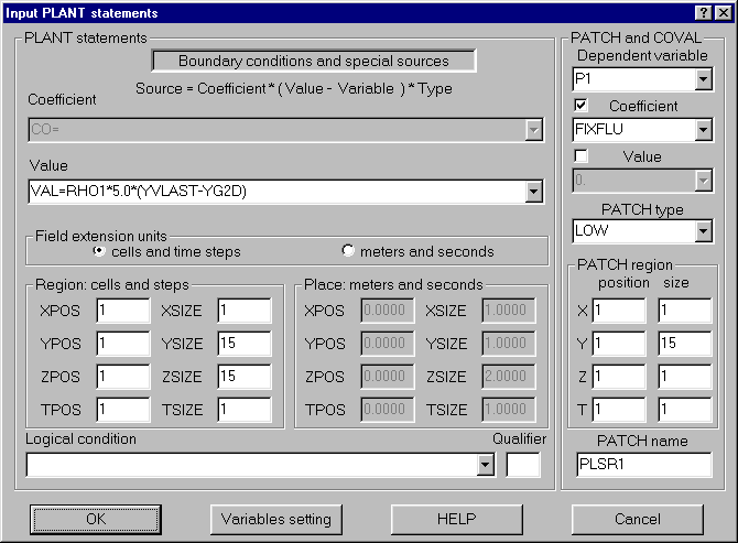
Make settings for P1 as shown in the image below. First select P1 from the list of dependent variables - the other input boxes will not become 'live' until a variable has been chosen.
Click 'OK' to close the dialog.
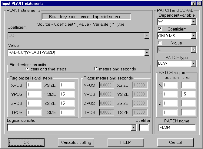
Click 'Add' again, and make settings for W1 as shown below.
Normally, each boundary condition is applied as a separate PATCH. In this case, we want the mass flow (P1), velocity and enthalpy conditions to be set by the same PATCH. Change the PATCH name in the bottom-right corner to PLSR1 - the name used for the P1 PATCH.
Click 'OK' to close the dialog.
Click 'Add' again, and make settings for TEMP as shown below. Remember to change the PATCH name to PLSR1.
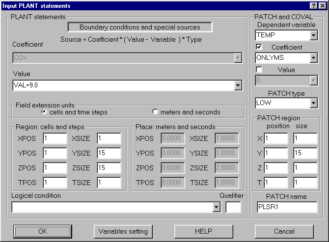
Click 'OK', then 'Exit' to leave the Plant menu.
In the PHOENICS-VR environment, click on 'Options', then 'Run version'.
For Earth, select 'Private'.
Click on 'Run', 'Solver'(Earth). and 'OK' to confirm running the solver.
Click on 'Yes' to allow the compilation and re-linking to proceed.
In the PHOENICS-VR environment, click on 'Run', 'Post processor',then GUI Post processor (VR Viewer) Viewer)' and view the velocity vectors, contours and isosurfaces. (Hint - set the slice direction to X).
