In this workshop the gas methane (CH4) will be used as the domain fluid.
The properties of this gas are not stored in the PROPS file so the user will have to introduce them using the Main Menu. The properties to be introduced are:
The workshop also shows how objects 'made' from 'Domain material' can be used to make holes in other solids.
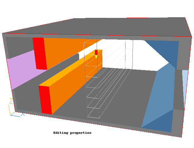
The geometry is shown below:

Start with an 'empty' case - click on 'File' then on 'Start New Case', then on 'Core', then click on 'OK'; to confirm the resetting.
Set domain Size and Activate Solution of Variables
Click on 'Main Menu'
Click on 'Geometry'
Click on 'Domain size' under 'Z-direction' and enter 0.5
Change X-Auto, Y-Auto and Z-Auto all to Manual by clicking on the buttons. In this tutorial we will manually set a coarse grid.
Click on 'Number of cells' and under X-direction enter 30. Under Z-direction enter 40. Leave Y-direction at 1.
Click on 'OK' to close the Grid mesh settings dialog.
Click on 'Models' and Leave the default 'Solution for velocities and pressure' to ON.
Switch on the Energy Equation, select Temperature and click on OK.
Click on OK.
Set the properties of the Fluid
Click on 'Properties'
Click on 'The current domain material is' dialogue box 'Gases' and select '42 dummy fluid'. Click on OK
Click on 'Edit properties of current material'
Change the following to:
DENSITY:
Click on Density 'CONSTANT' and select 'Ideal Gas'. Enter 16 for MOL-WT and 1.4 for GAMMA.
Switch storage to ON.
VISCOSITY:
Click on Viscosity 'CONSTANT' and select 'Linear in Tabs'. Click on OK.
Enter 5.96E-06 for A and 4.5838E-08 for B.
Switch storage to ON.
SPECIFIC HEAT:
Change specific heat from CP=1 to CP= 2230
CONDUCTIVITY:
Click on COND=10 and enter 3.42E-04
THERMAL EXPANSION COEFFICIENT:
Click on Beta=0 and enter 3.330E-03
Click on 'Previous Panel'
Click on 'Top Menu' and 'OK';.
Click 'Reset' on the Movement control panel, then 'Fit to window' to re-scale the view to fit the geometry.
Create the objects making up the scene
Click on the 'Object Management' button (O on the toolbar or
on the hand set). This will display a (currently empty apart from the domain) list of objects.
Create the UWALL object
Click on 'Object', 'New', 'New object', 'Blockage'.
Change Name to UWALL
Click on 'Size' to set the Size of object as:
XSize: tick 'To end'
YSize: tick 'To end'
ZSize: 0.02
Click on 'Place' to set the Position of object as:
XPos: 0.0
YPos: 0.0
ZPos: tick 'At end'
Click on 'General'.
Click on 'Attributes'
Click on 'Other materials', then 'Solids' and select '111 STEEL at 27 deg C'
The grid is too coarse to calculate accurate heat transfer coefficients. Change the Heat transfer coeff setting from 'Wall function' to 'User'. The default value of 10W/m2/K will suffice.
Click on OK/OK
Create LWALL object by duplication from UWALL.
Click on Duplicate button in the main control panel or toolbar
and then 'OK'.
Click twice on the new object and change the Name to LWALL.
Untick 'At-end' in Z, then move the new object to Zpos=0.0
Click on OK
Create WWALL1 Object
Click on 'Object', 'New', 'New object', 'Blockage'.
Change Name to WWALL1
Click on 'Size' to set the Size of object as:
XSize: 0.02
YSize: tick 'To end'
ZSize: 0.15
Click on 'Place' to set the Position of object as:
XPos: 0.0
YPos: 0.0
ZPos: 0.35
Click on 'General'
Click on 'Attributes'
Click on 'Other materials', then 'Solids' and select ‘111 STEEL at 27 deg C (C=1%)
Change the Heat transfer coeff setting from 'Wall function' to 'User'.
Click on OK/OK
Create WWALL2 object by duplication from WWALL1.
Click on Duplicate button in the VR Editor and 'OK'
Move the new object to Zpos=0
Click twice on the new object and change the Name to WWALL2. Click on OK.
Create EWALL1 object by duplication from WWALL2.
Click on Duplicate button in the VR Editor and 'OK'.
Double click on the newly duplicated object
Change the Name to EWALL1.
Change the position and size of the new object to:
XPos: tick 'At end' XSize: 0.05
YPos: 0.0 YSize: 'To end'
ZPos: 0.35 ZSize: 0.15
Click on OK.
Create EWALL2 object by duplication from WWALL2.
Click on Duplicate button in the VR Editor and 'OK'.
click twice in the newly duplicated object .
Change the Name to EWALL2
Change the position and size to:
XPos: 'At end' XSize: 0.05
YPos: 0.0 YSize: 'To end'
ZPos: 0.0 ZSize: 0.15
Click on OK.
Create Upper Wedge, WED1
Click on 'Object', 'New', 'New object', 'Blockage'.
Change Name to WED1
Click on 'Size' to set the Size of object as:
XSize: 0.15
YSize: 'To end'
ZSize: 0.13
Click on 'Place' to set the Position of object as:
XPos: 0.8
YPos: 0.0
ZPos: 0.35
Click on 'General' and then 'Shape'.
Click on Geometry dialogue box and select /PUBLIC/SHAPES/WEDGE. Click on 'Open'.
Click on 'Attributes'
Click on 'Other materials', then 'Solids' and select '111 STEEL at 27 deg C'
Change the Heat transfer coeff setting from 'Wall function' to 'User'.
Click on 'OK'
Click on 'Options' and 'Rotation options' set value to 16.
Click on OK/OK.
Create Lower Wedge by duplication from WED1
Click on Duplicate button in the VR Editor and 'OK'.
Click on the new object
Change the Name to WED2
Change the position and size of the new object to:
XPos: 0.8 XSize: 0.15
YPos: 0.0 YSize: 'To end'
ZPos: 0.02 ZSize: 0.13
Click on 'Options' and 'Rotation options'.
Set the value to 2. Click on OK/OK.
Create Upper Heat Source, HEAT1
Click on 'Object', 'New', 'New object', 'Blockage'.
Change Name to HEAT1
Click on 'Size' to set the Size of object as:
XSize: 0.07
YSize: 'To end'
ZSize: 0.18
Click on 'Place' to set the Position of object as:
XPos: 0.2
YPos: 0.0
ZPos: 0.3
Click on 'General'.
Click on 'Attributes'
Click on 'Other materials', then 'Solids' and select '103 COPPER at 27 deg C' and then 'OK'
Set Heat Source to 50W. Click on 'Adiabatic', select 'Fixed heat flux', and enter 50 for 'Value'.
Change the Heat transfer coeff setting from 'Wall function' to 'User'.
Click on OK/OK.
Create Lower Heat Source, HEAT2, by duplication from HEAT1
Click on Duplicate button in the VR Editor and 'OK'.
Click on twice on the new object.
Change Name to HEAT2
Click on 'Size' and set the Size of the new object as:
XSize: 0.07
YSize: 'To end'
ZSize: 0.18
Click on 'Place' and set the Position of the new object as:
XPos: 0.2
YPos: 0.0
ZPos: 0.02
Click on OK
Create blockage BLOCK1
Click on 'Object', 'New', 'New object', 'Blockage'.
Change Name to BLOCK1
Click on 'Size' and set the Size of object as:
XSize: 0.07
YSize: 'To end'
ZSize: 0.46
Click on 'Place' and set the Position of object as:
XPos: 0.5
YPos: 0.0
ZPos: 0.02
Click on 'Other materials', then 'Solids' and select '111 STEEL at 27 deg C'
Change the Heat transfer coeff setting from 'Wall function' to 'User'.
Click on OK
Create first hole in BLOCK1 - AIRHOL1 (must be created AFTER object BLOCK1 so that it overwrites the material properties of the blockage)
Click on 'Object', 'New', 'New object', 'Blockage'.
Change Name to Airhol1
Click on 'Size' and set the Size of object as:
XSize: 0.07
YSize: 'To end'
ZSize: 0.06
Click on 'Place' and set the Position of object as:
XPos: 0.5
YPos: 0.0
ZPos: 0.04
Click on 'General'.
Click on 'Attributes' and set material to Domain material.
Click on OK/OK
Create remaining holes in BLOCK1 by array-copying AIRHOL1
Click on the Array button
and enter:
Direction Dimension Pitch X 1 0.0 Y 1 0.0 Z 4 0.12 Click on OK
To see the hole objects, right-click on BLOCK1 and tick 'Wireframe'.
Create Inlet
Click on 'Object', 'New', 'New object', 'Inlet', then select the X plane for the inlet to lie in.
Change Name to INLET
Click on 'Size' and set the Size of object as:
XSize: 0.0
YSize: 'To end'
ZSize: 0.2
Click on 'Place' and set the Position of object as:
XPos: 0.0
YPos: 0.0
ZPos: 0.15
Click on 'General' and select Type: INLET.
Click on 'Attributes' and leave Ambient 20 degrees for temperature, and set 1.0 m/s for X-direction velocity.
Click on OK/OK.
Create Outlet
Click on 'Object', 'New', 'New object', 'Outlet', then select the X plane for the outlet to lie in.
Change Name to OUTLET
Click on 'Size' and set the Size of object as:
XSize: 0.0
YSize: 'To end'
ZSize: 0.2
Click on 'Place' and set the Position of object as:
XPos: 'At end'
YPos: 0.0
ZPos: 0.15
Click on 'General'
Click on the Type dialogue box and select OUTLET.
Click on OK/OK.
Set remaining solution control parameters.
Click on Main Menu
Click on 'Numerics' and set Total number of Iterations to 300.
Click on Top menu
Click on Ok
Set the Monitoring Point
Adjust Monitoring position using the 'Position' buttons to;
X 0.4
Y 0.5
Z 0.24
In the PHOENICS-VR environment, click on 'Run', 'Solver'(Earth), and click on 'OK'; to confirm running Earth.
In the PHOENICS-VR environment, click on 'Run', 'Solver' then 'Local solver(Earth)', and click on 'OK' to confirm running Earth.
To view:
To select the plotting variable:
To change the direction of the plotting plane, set the slice direction to X, Y or Z ![]()
To change the position of the plotting plane, move the probe using the probe position buttons
 .
.
To make the objects see-through, click the 'Wire-frame' toggle (to the right of the Macro button on the second row of buttons). This will make the temperature contours inside the solids visible.
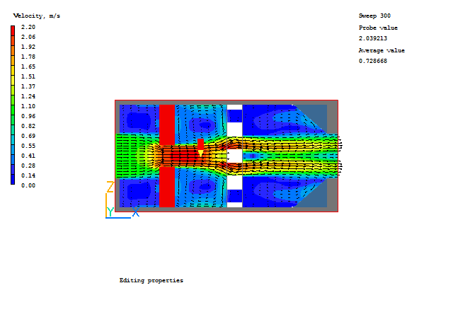
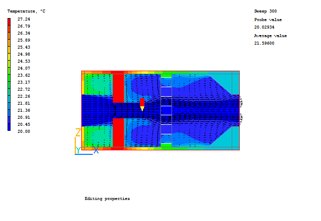
Typical plots from this case are:


In the PHOENICS-VR environment, click on 'Save as a case', make a new folder called 'Properties' (e.g.) and save as 'CASE1' (e.g.).