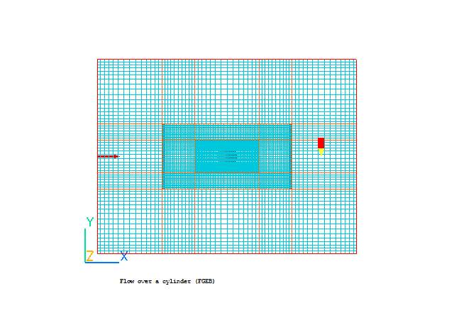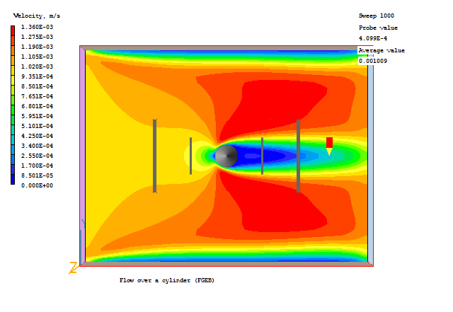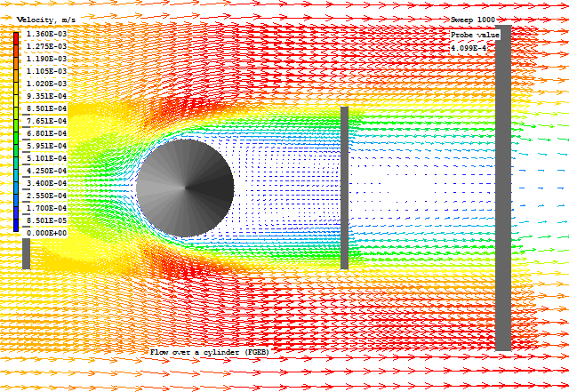
This workshop shows how to use a Fine Grid Volume to increase the local resolution. The case considered is the flow over a cylinder.

Start with an 'empty' case - click on 'File' then on 'Start New Case', then on 'Core', then click on 'OK'; to confirm the resetting.
Set domain size and activate solution of variables
Click on 'Main Menu'.
Set the title to 'Flow over a cylinder (FGEB)'
Click on 'Geometry'.
Set the Domain size to 8.0 m in X, 6.0 m in Y and 1.0 m in Z
Click 'OK' to close the Grid mesh settings dialog.
Click on 'Models'.
Solution for velocities and pressure: ON
Turbulence models: Laminar
Click on 'Top menu'.
Set the conditions on the faces of the domain:
Click on 'Domain Faces'.
Set 'Flow' to 'Yes' for the Xmin face.
Click 'Settings' for the Xmin face and set the X velocity to 0.001m/s. Given the diameter of the cylinder (0.6m) this gives a Reynolds number of around 60, which is below the limit for vortex shedding.
Set 'Open' to 'Yes' for the Xmax face.
Set 'Wall' to 'Yes' for the Ymin and Ymax faces.
Click on 'OK' to close the Domain Faces Dialogue Box, and 'OK' again to close the reminder to set / check boundary conditions.
Click on 'OK' to exit the Main Menu.
Click on the 'Reset' button on the movement control panel
Click on 'Fit to window' and 'OK'
Click on the 'Mouse' button and use mouse to rotate the view in X-Y plane.
Create blockage for CYLINDER
Click on 'Settings', 'New', 'New Object', 'Blockage'.
Name: Cylinder
Click on 'Size' and enter:
Xsize: 0.6
Ysize: 0.6
Zsize: 'To end'
Click on 'Place' and enter:
Xpos: 3.7
Ypos: 2.7
Zpos: 0.0
Click on 'Shape' and select the geometry: PUBLIC/SHAPES/cylinder
Click 'Options' and de-select 'Object affects grid'
Click on OK.
Create the first Fine-grid volume
Click on 'Settings', 'New' and 'New Object', 'Fine_grid_vol'.
Name: fine1
Click on 'Size' and enter:
Xsize: 4.0
Ysize: 2.0
Zsize: 'To end'
Click on 'Place' and enter:
Xpos: 2.0
Ypos: 2.0
Zpos: 0.0
Click on 'Attributes'.
Fineness X: 2
Fineness Y: 2
Fineness Z: 1
This will double the grid within the fine-grid object. You may click on the 'mesh toggle' button on the main control panel to view the grid
Click on OK/OK.
Create the second Fine-grid volume
Click on 'Settings', 'New', 'New Object', 'Fine_grid_vol'.
Name: fine2
Click on 'Size' and enter:
Xsize: 2.0
Ysize: 1.0
Zsize: 'To end'
Click on 'Place' and enter:
Xpos: 3.0
Ypos: 2.5
Zpos: 0.0
Click on 'Attributes'.
Fineness X: 2
Fineness Y: 2
Fineness Z: 1
This will double again the grid within the fine-grid object. You may click on the 'mesh toggle' button on the main control panel to view the grid
Click on OK/OK.
Setting the Probe Location
Click on the probe icon
on the toolbar or double-click the probe itself, and move the probe to X=7.0, Y=3.0, Z=0.5.
Set remaining solution control parameters
Click on 'Main menu'.
Click on 'Numerics'.
Total number of iterations: 1000
Click on 'Top menu'.
Click on OK.
In the PHOENICS-VR environment, click on 'Run', 'Solver' (Earth), and click on 'OK'; to confirm running Earth.
In the PHOENICS-VR environment, click on 'Run', 'Post processor',then GUI Post processor (VR Viewer) . Click 'OK' on the file names dialog to accept the default files.
To view:
To select the plotting variable:
To change the direction of the plotting plane, set the slice direction to X, Y or Z ![]()
To change the position of the plotting plane, move the probe using the probe position buttons
 .
.
Typical plots from this case are:


In the PHOENICS-VR environment, click on 'Save as a case', make a new folder called 'Finegrid' (e.g.) and save as 'CASE1' (e.g.).