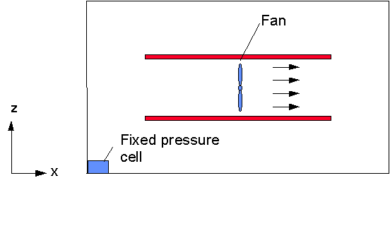
In this workshop it is shown how to specify an internal momentum source in PHOENICS-VR as a fan object or, alternatively, as an internal mass source-sink, represented as an inlet-outlet pair.
With the fan-type object, the user can fix the velocity at that location. This just circulates the air already in the domain. The fan-method is demonstrated in the first section.
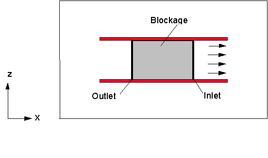
A similar flow can be set up by replacing the fan object by an inlet-outlet pair, separated by a small blocked region. This continually injects fresh air, which then leaves the domain. The inlet-outlet pair method is demonstrated in the second section.
Note that this demonstration is interesting because the fan is internal; if the fan object were at a boundary, then the fan object would work like an ordinary inlet.
Start with an 'empty' case - click on 'File' then on 'Start New Case', then on 'Core', then click on 'OK'; to confirm the resetting.
Set the domain size, and activate solution of the required variables:
Click on (Main) 'Menu' button on the handset and then on 'Geometry'.
Change the Z-domain size to 0.62.
Click 'OK' to close the Grid mesh settings dialog.
Click on 'Models'.
Leave 'Solution for velocities and pressure' to ON.
For 'Turbulence models' select 'Standard KE' for from the 'KE variants' list.
Create the internal surfaces of the duct:
Click on 'Domain Faces'.
Set 'Wall' to 'Yes' for the Xmin, Xmax, Zmin and Zmax faces.
Click on 'OK' to close the Domain Faces Dialogue Box, and 'OK' again to close the reminder to set / check boundary conditions. The default settings are fine.
Click on 'Top Menu' and then on 'OK';.
Click on 'Reset', 'fit to window' and 'OK'
Change the view to X-Z plane with Z up.
Create the lower internal wall:
Click on 'Settings', 'New', 'New Object', 'Blockage' on the top bar menu of the VR-Editor to bring up the Object specification dialog box.
Change Name to 'WALL-1'.
Click on 'Size' and set Size of the object as:
Xsize: 0.6
Ysize: 'To end'
Zsize: 0.02
Click on 'Place' and set Position of the object as:
Xpos: 0.2
Ypos: 0.0
Zpos: 0.2
Click on 'OK';.
Create the upper internal wall by duplicating WALL-1:
Click on the 'Duplicate object or group' button and 'OK'
Use Z Position buttons on the handset to move the resulting object to
Xpos: 0.2
Ypos: 0.0
Zpos: 0.4
Double click on the resulting object
Change Name to 'WALL-2'.
Click on 'OK';.
Create the fan object:
Click on 'Settings', 'New' and 'New Object', 'Fan', 'X plane'.
Change Name to 'Fan'.
Click on 'Size' and set Size of the object as:
Xsize: 0.0
Ysize: 'To end'
Zsize: 0.18
Click on 'Place' and set Position of the object as:
Xpos: 0.5
Ypos: 0.0
Zpos: 0.22
Click on 'General'.
Click on Attributes and change the x-direction velocity to 1.0 m/s.
Click on OK.
Click on 'OK';.
Create a fixed pressure point - the domain is closed, and the fluid is incompressible. Without a fixed pressure point the pressure level is undefined.
Click on 'Settings', 'New' and 'New Object', 'Pressure_relief'
Change Name to 'Fixedp'.
Click on 'Size' and set Size of the object as:
Xsize: 0.03
Ysize: 'To end'
Zsize: 0.03
Note that the size set for a 'Pressure_relief' object is only a guide - the actual size will be set to just fill the cell containing the centre of the object.
Click on 'OK'.
Set the grid:
Click on the 'Mesh toggle' button. The default mesh (shown as orange and blue lines) will appear on the screen. The auto-generated grid is perfectly adequate for the tutorial, but in order to practice setting the grid, we are going to alter the Z (vertical) grid.
Click anywhere on the image, and the 'Gridmesh settings' dialog box will appear. Switch the Z grid from 'Z-Auto' to 'Z-Manual', then click Edit all regions in Z direction. Make the following settings:
Region Cells Distribution Power Symmetric 1 6 Power law -1.5 No 2 3 Power law 1 No 3 15 Power law 1.2 Yes 4 3 Power law 1 No 5 6 Power law 1.5 No We will also change the auto-mesh settings for the X grid to make it a little coarser. Click Edit all regions in X direction.
The smallest cell (as a percentage of the domain size) is defaulted to 1%. Change this to 2% and click 'Apply'. The number of cells in X will reduce to 32.
Click on 'OK' twice to close the dialog boxes.
The mesh will now be shown as blue and orange lines. The orange lines are 'regions', defined by the bounding boxes of the objects.
(Optional) Open the 'Gridmesh settings' dialog again by clicking on the grid, and click 'Edit all regions' in Z again. Change the signs of the powers in regions 1 and 5 to be 1.5 and -1.5 respectively. Click on 'OK' twice to close the dialog boxes. How has the grid changed? Now restore the settings in the table above.
Click on 'Mesh toggle' again to turn off the mesh display.
Set the remaining solution control parameters:
Click on Main 'Menu', then on click on Numerics and enter 500 in the 'Total number of iterations' dialogue box.
Click on 'Relaxation control' and switch 'Automatic convergence control' OFF, then click 'Reset solution defaults'.
Click on 'Top Menu' and 'OK'.
In the PHOENICS-VR environment, click on 'Run', 'Solver' (Earth), and click on 'OK'; to confirm running Earth.
In the PHOENICS-VR environment, click on 'Run', 'Post processor',then GUI Post processor (VR Viewer) . Click 'OK' on the file names dialog to accept the default files.
To view:
To select the plotting variable:
To change the direction of the plotting plane, set the slice direction to X, Y or Z ![]()
To change the position of the plotting plane, move the probe using the probe position buttons
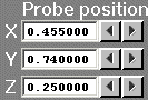
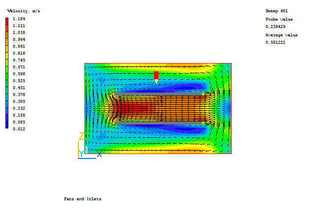
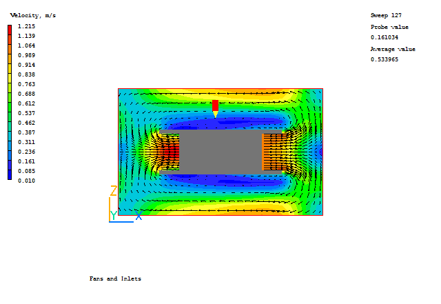
A typical plot from this case is:
In the PHOENICS-VR environment, click on 'Save as a case', make a new folder called 'INLETS' (e.g.) and save as 'CASE1' (e.g.).
Change the fan (fixed velocity) into an inlet (fixed mass flow)
Click on the 'Object management' button on the handset.
Select the object, FIXEDP and click on 'Action' and 'Delete object(s)'.
Click on 'Yes' to confirm the action.
Double click on the FAN object to bring up the object specification dialog box.
Change the Type from FAN to INLET.
Click on Attributes and enter 1.0 in the x-direction dialogue box.
Change Object side to High.
Click on 'OK';.
Click on 'Place' and change the position to:
Xpos: 0.7
Ypos: 0.0
Zpos: 0.22
Click on 'OK';
Create the blockage separating the inlet and outlet:
Click on 'Settings', 'New' and 'New Object'. Select 'Blockage' from the list of object types.
Click on 'Size' and 'Place' to change the following to:
Xpos: 0.3 Xsize: 0.4
Ypos: 0.0 Ysize: 1.0
Zpos: 0.22 Ysize: 0.18
Click on 'OK';
Create the outlet:
Click on 'Settings', 'New' and 'New Object'. Select 'Outlet' from the list of object types.
Select the X plane and click OK.
Change the Name to 'OUT'.
Click on 'Size' and 'Place' to change the following to:
Xpos: 0.3 Xsize: 0.0
Ypos: 0.0 Ysize: 1.0
Zpos: 0.22 Zsize: 0.18
Click on 'General'.
Click on 'Attributes' and check that the Object side is set to 'Low'.
Click on OK/OK.
Click on 'Run', 'Solver' (Earth), and click on 'OK'; to confirm running Earth.
The object FAN should be acting as a 'source' and the object OUT should be acting as a 'sink'.
Investigate the following combination of Attributes for the FAN and OUT objects
| Object name | Fan | Out |
| Object type | Inlet | Outlet |
| Attributes | Velocity = -1.0 m/s | pressure condition |
| Object side | High | Low |
| Object type | Outlet | Inlet |
| Attributes | pressure condition | Velocity = -1.0 m/s |
| Object side | High | Low |
| Object type | Outlet | Inlet |
| Attributes | pressure condition | Velocity = +1.0 m/s |
| Object side | High | Low |
Each run can be saved as a different case in the INLETS folder.