Click on the 'Object Management' button (![]() on the toolbar or
on the toolbar or
![]() on the hand set). This will display a (currently empty
apart from the domain) list of objects.
on the hand set). This will display a (currently empty
apart from the domain) list of objects.
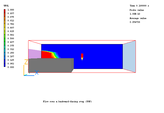
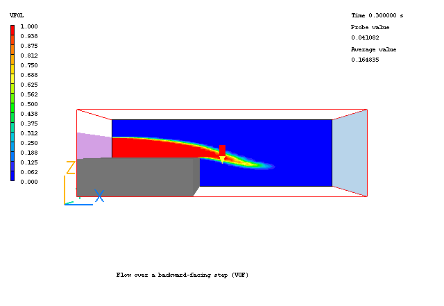
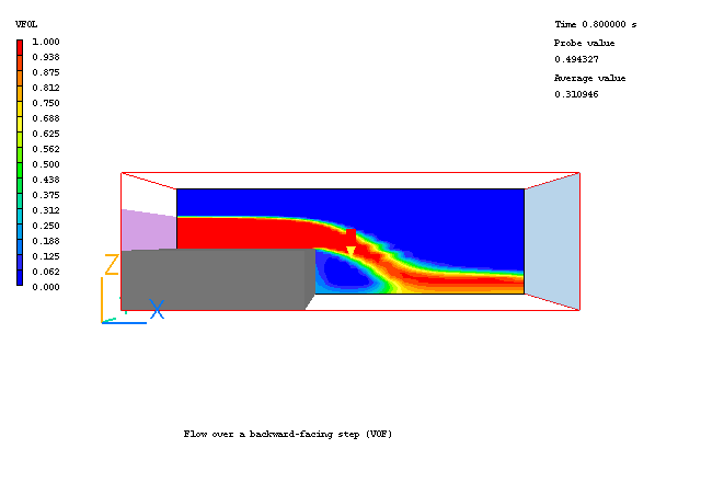
The example simulates unsteady, laminar flow over a backward-facing step of 0.13m in a two-dimensional channel of width 0.3m. The length of the channel is 1m. The water is coming through a narrow inlet between the step. The example shows how to activate VOF in the VR-Editor for a free surface problem.
A complete step-by-step guide, showing how to set the case from the default mode of operation, is provided below.
From the system level:
To enter the PHOENICS-VR environment, click on the PHOENICS icon on the desktop, or click on Start, programs, PHOENICS, PHOENICS.
In PHOENICS-VR environment,
Start with an 'empty' case - click on 'File' then on 'Start New Case', then on 'Core', then click on 'OK' to confirm the resetting.
To enter VR Editor:
This is the default mode of operation.
Set the domain size and time steps:
Click on 'Menu' (Main Menu) on the VRE-Editor panel; and set 'Flow over a backward-facing step (VOF)' as the Title.
Click on 'Geometry'.
Change 'Steady' to 'Transient'
Click 'Time step settings' button and set
Time at the end of last step to 0.5 s
Last step number to 500
Click on 'Apply' and 'OK'.
Change the x-domain size to 1.0.
Change the y-domain size to 1.0.
Change the z-domain size to 0.3.
Click on 'OK' to close the Grid mesh settings dialog.
Click on 'OK' to exit from 'Menu'.
Click on 'Reset' and then on 'Fit to window'/'OK'.
Activate solution of the required variables and models
Click on 'Menu'; and the on 'Models'.
Leave 'Solution for velocities and pressure' to ON.
Click on 'Turbulence models' and select 'Laminar'/'OK'.
Click on Free-Surface models; and then choose VOF - THINC.
Leave settings for cut-off values for interface sharpening as default 0.001 and 0.999.
Leave the surface tension as 0.0.
Specify properties
Click on 'Properties'.
Leave the default settings for the 'light fluid' and the 'heavy fluid' they are '0 Air at 20 C deg, 1 atm' and '67 Water at 20 deg C' respectively.
Click on Property 'Storage' and set 'ON' for Density and Viscosity, then on 'Previous panel'.
Keep the default setting for Domain initially full of: Light fluid
Sources settings
Click on 'Sources'
Set 'Gravitational forces' ON and click 'OK'.
Set 'Buoyancy model' to CONSTANT
Change 'Gravitational acceleration' to 0.0 in X and Y directions and -9.81 in Z.
Numerical settings
Click on 'Numerics'.
Set 'Total number of iterations' to 10.
Click 'Previous panel'
Output settings
Click Write flow field settings button and set 'Intermediate field dumps' to ON, 'Step frequency' to 10 and select a letter, say 'N' for ;Start letter for solution file'.
Click 'Previous panel', and then on 'Top menu' and 'OK' to exit from 'Menu'.
Create the objects making up the scene
Click on the 'Object Management' button (
on the toolbar or
on the hand set). This will display a (currently empty apart from the domain) list of objects.
Create a Blockage for the step
Click on 'Object', 'New','New Object', 'Blockage'.
Change name to BLK .
Click on 'Size' and set Size of the object as:
Xsize: 0.4
Ysize: 'To end'
Zsize: 0.13
Click 'OK' to exit from the Object Dialogue Box.
Create the Inlet
Click on 'Object', 'New','New Object', 'Inlet'. Select the X plane for the inlet to lie in.
Change name to INLET.
Click on 'Size' and set Size of the object as:
Xsize: 0
Ysize: 'To end'
Zsize: 0.0912
Click on 'Place' and set Position of the object as:
Xpos: 0
Ypos: 0.
Zpos: 0.13
Click on 'General'.
Click on 'Attributes'
Set Inlet density to Heavy
Set velocity in X-direction at 1.5 m/s.
Click on 'OK' twice to exit from the Object specification Dialogue Box.
Create the outlet
Click on 'Object', 'New','New Object', 'Outlet'. Select the X plane for the outlet to lie in.
Change name to OUT.
Click on 'Size' and set Size of the object as:
Xsize: 0.0
Ysize: 'To end'
Zsize: 'To end'
Click on 'Place' and set Position of the object as:
Xpos: 'At end'
Ypos: 0.0
Zpos: 0.0
Click on 'OK' to exit from the Object specification Dialogue Box.
Setting the Probe Location
Before running the solver,it is a good idea to place the probe in a suitable place to monitor the convergence of the solution. Too close to an inlet, and the value will settle down very quickly before the rest of the solution. Placed in a recirculation zone, it may still show traces of change even though the bulk solution is converged. In this case, somewhere downstream of the step is fine.
Click on the probe icon
on the toolbar or double-click the probe itself, and move the probe to X=0.5, Y=0.5, Z=0.1.
Setting the Grid
Click the mesh toggle
to display the grid. The orange lines are region boundaries, located at the edges of the objects. The blue lines are 'ordinary' grid lines inserted by the auto-mesher. In this case, the default grid in X (36 cells) and Z (40 cells) is adequate.
In the PHOENICS-VR environment, click on 'Run', 'Solver'(Earth), and click on 'OK'; to confirm running Earth.
In the PHOENICS-VR environment, click on 'Run', 'Post processor',then GUI Post processor (VR Viewer)'. Click 'Use intermediate step files' The 'Plot step number' will show 40. Then click on 'OK'.
To view:
Turn the Contour display on, then select VFOL from the 'Select
variable' button ![]() . Click the animation button
. Click the animation button ![]() to show the
evolution of the water volume fraction contour with time.
to show the
evolution of the water volume fraction contour with time.
A few selected plots at various time steps are shown below.
 |
 |
Time = 0.1 s |
Time = 0.3 s |
 |
 |
| Time = 0.6 | Time = 0.8 |
The PHOENICS Encyclopedia contains further details under the headings:
Volume of Fluid and Scalar Equation Method
Library examples can be found in the multi-Phase flow library, which can be accessed from the VR-Editor ->File menu->Load from libraries ->/Browse/Option library: Advanced multi-phase/Volume of Fluid Model (VOF) or Scalar-Equation Model(SEM).
In the PHOENICS-VR environment, click on 'Save as a case', make a new folder called 'FREES', select the new folder, and save as 'SEM', where n is 1,2,3 or 4 depending on the combustion option.