This tutorial shows how to use In-Form statements in the Q1 file so as to set an inlet-boundary-layer profile in which the velocity varies in accordance with the 1/7th power of height above the ground. It calculates the two-dimensional flow over a blockage, representing a long building.
It appears in the 'core' input-file library as case 658.
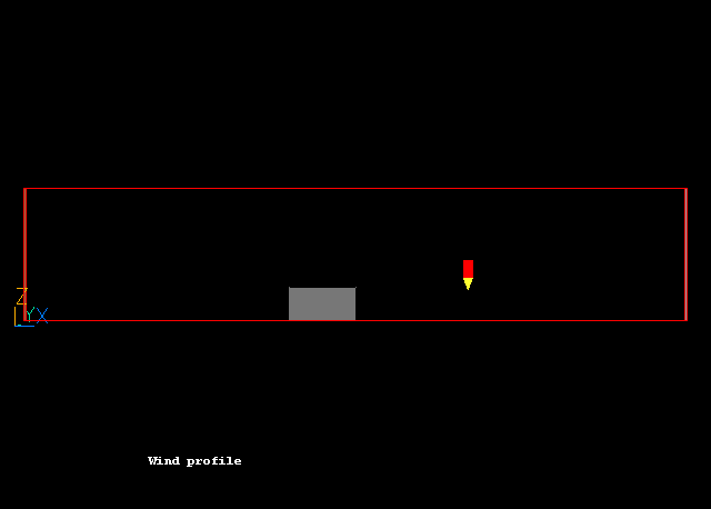
The geometry is shown in Figure 1 below. The inlet is on the left (brown) and two outlets are on the top and right (blue). The fluid flows from low-x to high-x.

Figure 1. The geometry
The inlet velocity profile will be set to Uin = 5z(1/7)
A complete step-by-step guide, showing how to set the case from the default mode of operation, is provided below.
However, if you wish to proceed directly to the In-Form-related instructions, click here.
From the system level:
To enter the PHOENICS-VR environment, click on the PHOENICS icon on the desktop, or click on Start, programs, PHOENICS, PHOENICS.
In PHOENICS-VR environment,
Start with an 'empty' case - click on 'File' then on 'Start New Case', then on 'Core'', then click on 'OK'; to confirm the resetting.
To enter VR Editor:
This is the default mode of operation.
Set the domain size and grid numbers:
Click on 'Menu' (Main Menu) on the VRE-Editor panel; and then on 'Geometry'.
Change the x-domain size to 100.0.
Leave the y-domain size at 1.0.
Leave the z-domain size at 20.0.
Turn the 'Auto' settings for X and Z to 'Manual' in X and Z, then set 'number of cells' to 50 in the x-direction and 20 in the z-direction.
Click on 'Edit all regions in Z direction'. Set the power for region 1 to 1.4. This will make the Z grid finer near the ground. Click 'OK'.
Click on 'OK' to close the Grid mesh settings dialog.
Models settings
Click on 'Models'.
Turn 'Solution for velocities and pressure' to ON.
Click on LAMINAR (Turbulence models) and choose the KE Variants. From the next dialog choose KEMMK. This model is suitable for atmospheric boundary layers.
Enter numerical settings
Click on 'Numerics'.
Set 'Total of number of iterations' to 400
Click 'Previous panel'
Click on 'Top menu' and then on 'OK' to exit from 'Menu'.
Create Objects and specify boundary conditions
Click on the 'Object Management' button (O on the toolbar or ![]() on the hand set). This will display a (currently empty
apart from the domain) list of objects.
on the hand set). This will display a (currently empty
apart from the domain) list of objects.
Create the inlet
In the Object management dialog, click on 'Object', 'New' and 'New Object', 'User-Defined'.
Change name to IN.
Set Position and Size of the object as:
Xpos: 0.0 Xsize: 0.0
Ypos: 0.0 Ysize: 1.0
Zpos: 0.0 Zsize: 20.0
Click on 'Attributes', then on 'Edit InForm 13'. The In-Form editor will appear.
Between the lines SAVE13BEGIN and SAVE13END which appear in the input window, type in the following commands:
  SAVE13BEGIN
   **DEFINE CONSTANT PARAMETER**
REAL(GA,GD,GE)
GA=5.0
GD=0.05
GE=20.0

   **DEFINE VIN & MDOT**
CHAR(VIN,MDOT)
VIN=GA*(ZG)^(1.0/7.0)
MDOT=:RHO1:*:VIN:

   **DEFINE SOURCE OF VARIABLES**
(SOURCE OF P1 AT IN IS :MDOT: WITH AREA)
(SOURCE OF U1 AT IN IS :MDOT:*:VIN: WITH AREA)
(SOURCE OF KE AT IN IS :MDOT:*(GD*:VIN:)^2.0 WITH AREA)
(SOURCE OF EP AT IN IS :MDOT:*0.1643*KE^1.5/(GD*GE) WITH AREA)
  SAVE13END
Click on 'File', then 'Save current block'. Close the In-Form Editor.
The line VIN=GA*(ZG)^(1.0/7.0) sets the velocity profile to be:
Vin = a.Z(1/7)
where a is 5.0 (GA above), and Z is the height. The next line multiplies the velocity by the density to get a mass flux. The following lines set the mass, momentum and K - e sources for the object IN. The 'with area' qualifier states that the source is 'per unit area'.
Note that the easiest way to insert these lines is to highlight them in the browser window, right-click and copy, then paste into the In-Form Editor window.
Click 'OK' to exit from the Object Dialogue Box.
Create the outlets
In the Object management dialog, click on 'Object', 'New' and 'New Object', 'Outlet' and X plane.
Change name to OUT.
Set Position and Size of the object as:
Xpos: 100.0 Xsize: 0.0
Ypos: 0.0 Ysize: 1.0
Zpos: 0.0 Zsize: 20.0
Click 'OK' to exit from the Object Dialogue Box.
In the Object management dialog, click on 'Object', 'New' and 'New Object', 'Outlet' and Z plane.
Change name to SKY.
Set Position and Size of the object as:
Xpos: 0.0 Xsize: 100.0
Ypos: 0.0 Ysize: 1.0
Zpos: 20.0 Zsize: 0.0
Click 'OK' to exit from the Object Dialogue Box.
Create the blockage
In the Object management dialog, click on 'Object', 'New' and 'New Object', 'Blockage'.
Change name to BLOCK.
Set Position and Size of the object as:
Xpos: 40.0 Xsize: 10.0
Ypos: 0.0 Ysize: 1.0
Zpos: 0.0 Zsize: 5.0
Click 'OK' to exit from the Object Dialogue Box.
Create the ground
In the Object management dialog, click on 'Object', 'New' and 'New Object'.
Change name to GROUND.
Set Position and Size of the object as:
Xpos: 0.0 Xsize: 100.0
Ypos: 0.0 Ysize: 1.0
Zpos: 0.0 Zsize: 0.0
Define Type: Plate
Click 'OK' to exit from the Object Dialogue Box.
All settings are now complete.
You are advised to move the probe (small red pencil sign) to the position shown in Figure 1 (roughly X=67.0, z=5.0) before running the Solver, EARTH.
In the PHOENICS-VR environment, click on 'Run', 'Solver' then 'Local solver(Earth)', and click on 'OK'; to confirm running Earth.
In the PHOENICS-VR environment, click on 'Run', 'Post processor',then GUI Post processor (VR Viewer) Viewer)'. Click 'OK' on the file names dialog to accept the default files.
To view:
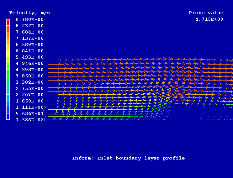
Figure 2 shows the velocity vectors.

Figure 2. Velocity vectors
In the PHOENICS-VR environment, click on 'Save as a case', make a new folder called 'INFORM', select the new folder, and save as 'WIND'.