The case considered is the laminar combustion of methane (CH4) in air (77% Nitrogen, 23% Oxygen) to form water vapour (H2O) and carbon dioxide (CO2) through a global one-step Arrhenius reaction. The geometry is a cylindrical combustor with annular inlets for air and two fuel streams. The case is solved on a 2d axisymmetric cylindrical-polar solution domain and the transport properties and combustion process are modeled using CHEMKIN. This case is identical to CHAM Library Case 644.
Please note that this example is designed to show how to set up a CHEMKIN model in PHOENICS. It is not for the purpose of validation.
Accessing PHOENICS-VR.
From the system level:
To enter the PHOENICS-VR environment, click on the PHOENICS icon on the desktop, or click on Start, programs, PHOENICS, PHOENICS.
In PHOENICS-VR environment,
Start with an 'empty' case - click on 'File' then on 'Start New Case', then on 'Core', then click on 'OK'; to confirm the resetting.
To enter VR Editor:
This is the default mode of operation.
Set the domain size and grid numbers:
Click on 'Menu' (Main Menu) on the VE-Editor panel and set 'Combustion: CHEMKIN' as the Title.
Click on 'Geometry'.
Please note that CHEMKIN uses CGS units, even though the dialogs will still display SI units.
Click on 'Cartesian' under co-ordinate system; and select 'Cylindrical-polar' and then on 'OK'.
Leave 'Inner radius' at 0.0 and 'tolerance' at 1.e-3.
Change the x-domain size to 0.1 radians.
Change the y-domain size to 3.0 (cm)
Change the z-domain size to 24.0 (cm)
Set 'number of cells' to 1 in the x-direction, 30 in the y-direction and 50 in the z-direction.
Click on 'OK' to close the Grid mesh settings dialog.
Click on 'OK' to exit from 'Menu'.
Click on 'Reset' button on the movement panel.
Click View -X and Up +Y
Click on 'Fit to Window'
Activate solution of the required variables and models
Click on 'Menu'; and then on 'Models'.
Leave 'Solution for velocities and pressure' to ON.
Click on ENERGY EQUATION; and then choose TEMPERATURE.
Click on 'Turbulence models' and select LAMINAR.
Click 'Settings' next to 'Solution control/Extra variables' and change 'Whole-field' for TEM1 from 'Y' to 'N'.
Click 'Previous panel', then 'Top Menu' and 'OK' to close the Main Menu.
The CHEMKIN model is set by a set of CHEMKIN commands described in the Encyclopaedia. Please note that the CHEMKIN commands can not at present be made in the VR-Editor.
The VR-Editor settings and PIL settings need to be combined in the Q1 file in order to complete the entire setting of the input data.
Once the geometry and models settings are completed, click on 'File', 'Open file for editing', 'Q1' to open and edit the Q1 file. Click 'Yes' when prompted to save the current VR settings to Q1.
Add the following PIL commands in Group 7:
The easiest way to do this is to highlight the text in the browser, right-click and copy it, then paste it into the Q1 at the end of Group 7.
After the above editing is completed, save the Q1 file and exit the text editor. Allow the VR-Editor to reload the Q1 on exit from the file editor. We can now continue the rest of the settings through the VR-Editor.
CHEMKIN data file
The user should edit and create a CHEMKIN mechanism file named CH4.CKM with the following contents:
Save this file. Note that the species listed above are the same as in the CHEMKIN(SPECIES... command added to the Q1. Also, note that the line containing the reaction data is divided into two entries. The first defines the reaction mechanism while the second contains the Arrhenius rate coefficients A = 6.456 10 21 cm.mol.s.K, β = 0, and E = 8130 cal/mol, which appear in the following expression for the forward rate coefficient: kf=A Tβ exp(-E/Ro T) where Ro is the universal gas constant in cal/(mol.K).
To generate the CHEMKIN link file, click 'Run', 'Pre-processor', 'CHEMKIN Interpreter'. In the dialog that appears, click 'Browse', and navigate to the CH4.CKM file and select it. Click OK to run the interpreter. The result should be the files ch4.lis, ch4ckln and ch4mcln in the current working directory.
Specify properties
Click on ‘Menu’ and then ‘Properties’.
Toggle ‘Use property table’ to OFF
Change Density, Viscosity, Specific Heat and Conductivity from their current settings to CHEMKIN.
Toggle Storage to ON for all the properties.
Click 'Page Dn' button.
Set the Thermal expansion coefficient to 0.0
Set the Temperature units to 'Kelvin'.
Set "Initialize from ambient" to off.
Set the Reference Pressure to 0.0.
Click Advanced Settings PIL. Then set PRNDTL for CH4, O2, CO2 and H2O to -GRND9 which instructs PHOENICS to use CHEMKIN to calculate the diffusion coefficients for these variables. (use the <> buttons to scroll the list of variables)
Click 'Previous panel'.
Set Initial values
Click on 'Initialisation'.
Set the initial value of W1 to 50cm/s, O2 to 0.23 and N2 to 0.77.
Set the initial value of TEM1 to 500 Kelvin
Source settings
Click on 'Sources'
Click on 'Page Dn' and then click 'Advanced Settings PIL'. Type CHEMK1 in the 'New' box, then click 'Apply'. Change the Type from CELL to VOLUME. Set the Coefficients and Values as follows:
Variable CH4 O2 H20 CO2 TEM1 Coefficient GRND9 GRND9 GRND9 GRND9 GRND9 Value GRND9 GRND9 GRND9 GRND9 GRND9
Click 'Previous panel'.
Enter numerical settings
Click on 'Numerics'.
Set 'Total number of iterations' to 4000
Click 'Relaxation control'.
Automatic Convergence Control - OFF, then 'reset solution defaults'.
Make the following relaxation settings:
V1 W1 CH4 O2 CO2 H2O TEM1 Falsdt 1.0E-3 Falsdt 1.0E-3 Falsdt 1.0E-3 Falsdt 1.0E-3 Falsdt 1.0E-3 Falsdt 1.0E-3 Falsdt 5.0E-5
Click 'Previous panel'.
Set Monitoring Options
Click 'Output' and 'Settings' next to Field Printout. Set 'OUTPUT 5 SPOT' and 'OUTPUT 6 TABL' to Y for CH4, N2 and DEN1. This will make the values of these variables at the probe location appear in the solver convergence monitor graph.
Click 'Previous panel', 'Top Menu' then 'OK' to close the Main Menu.
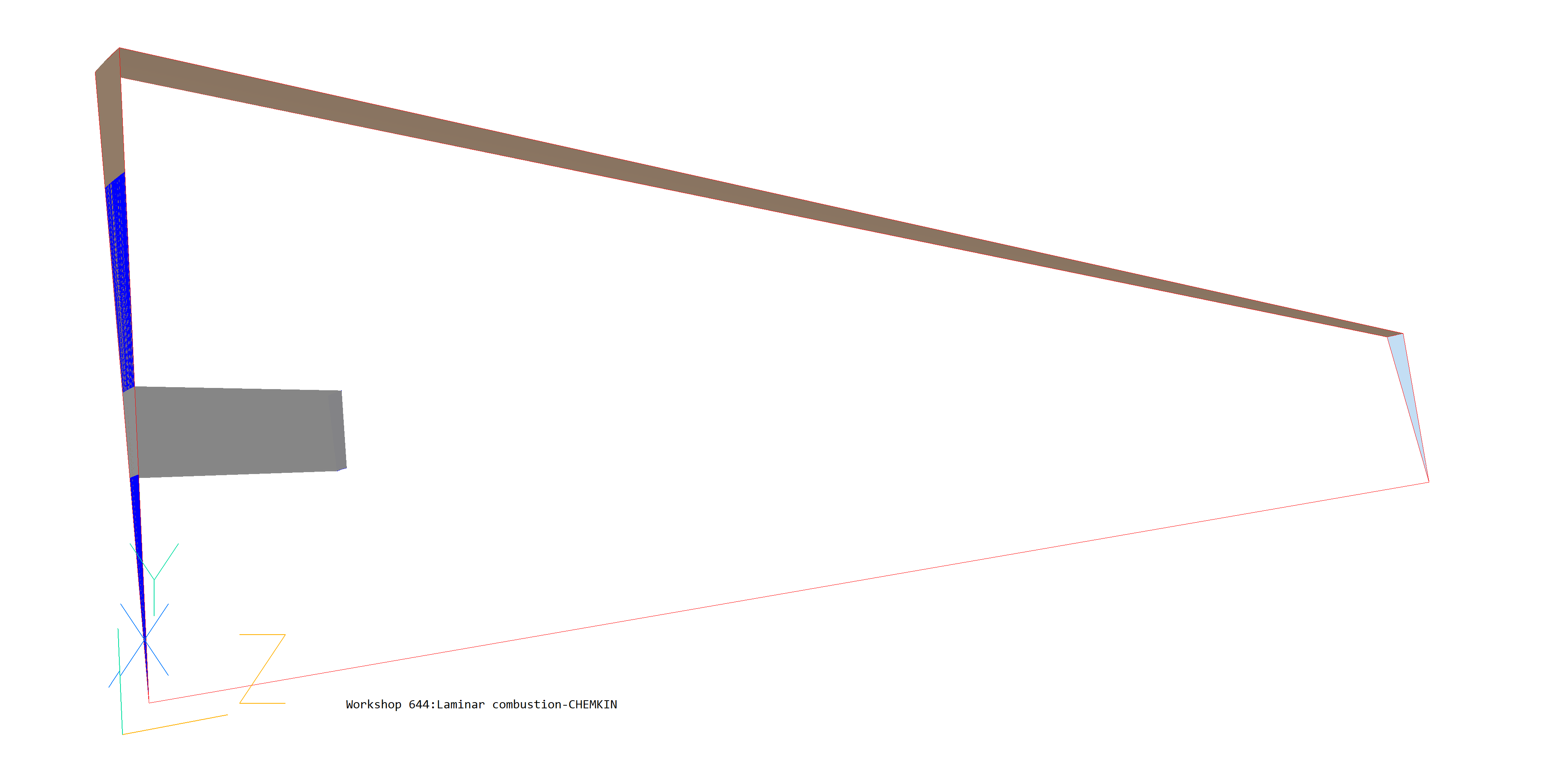
Create Objects and specify boundary conditions
Create a divider
Click on 'Settings', 'New', 'New Object', 'Blockage'.
Change the name to DIVIDER.
Click on 'Size' and set Size of the object as:
Xsize: 'To end'
Ysize: 0.4
Zsize: 1.0
Click on 'Place' and set POSITION of the object as:
Xpos: 0.0
Ypos: 1.0
Zpos: 0.0
Click 'OK'
Create the Oxidant Inlet
Click on 'Settings', 'New', 'New Object', 'User_defined'.
Change name to OXIN
Click on 'Size' and set Size of the object as:
Xsize: 'To end' 0.1
Ysize: 0.4
Zsize: 0.0
Click on 'Place' and set POSITION of the object as:
Xpos: 0.0
Ypos: 1.0
Zpos: 1.0
Click on 'General'.
Click on Attributes, and make the following settings:
In the 'New' entry box, type NOCPCK1, then click 'Apply'. A new PATCH command will be created. Change the TYPE from CELL to LOW. Make the following settings for Coefficient and Value:
P1 W1 O2 TEM1 Coefficient FIXFLU 0.0 0.0 0.0 Value GRND9 300.0 0.24 GRND9
This sets the inlet velocity to 300 cm/s, and the inlet mass-fraction of Oxygen to 0.24.
In the 'PIL command' entry box at the top of the dialog type:
SPEDAT(SET,NOCPCK1,TINLET,R,350)
This sets the inlet temperature to 350 Kelvin
Click 'Apply', then close the Attributes and Object specification dialogs.
Create the first fuel Inlet
Click on 'Settings', 'New', 'New Object', 'User_defined'.
Change name to FUIN1
Click on 'Size' and set Size of the object as:
Xsize: 'To end'
Ysize: 1.0
Zsize: 0.0
Click on 'General'.
Click on Attributes, and make the following settings:
In the 'New' entry box, type NOCPCK2, then click 'Apply'. A new PATCH command will be created. Change the TYPE from CELL to LOW. Make the following settings for Coefficient and Value:
P1 W1 CH4 TEM1 Coefficient FIXFLU 0.0 0.0 0.0 Value GRND9 100.0 1.0 GRND9 This sets the inlet velocity to 100 cm/s, and the inlet mass-fraction of Methane to 1.0.
In the 'PIL command' entry box at the top of the dialog type:
SPEDAT(SET,NOCPCK2,TINLET,R,350)
Click 'Apply', then close the Attributes and Object dialogs.
Create the second fuel Inlet
Click on 'Settings', 'New', 'New Object', 'User_defined'.
Change name to FUIN2
Click on 'Size' and set Size of the object as:
Xsize: 'To end'
Ysize: 1.0
Zsize: 0.0
Click on 'Place' and set Position of the object as:
Xpos: 0.0
Ypos: 1.4
Zpos: 0.0
Click on 'General'.
Click on Attributes, and make the following settings:
In the 'New' entry box, type NOCPCK3, then click 'Apply'. A new PATCH command will be created. Change the TYPE from CELL to LOW. Make the following settings for Coefficient and Value:
P1 W1 CH4 TEM1 Coefficient FIXFLU 0.0 0.0 0.0 Value GRND9 50.0 1.0 GRND9 This sets the inlet velocity to 50 cm/s, and the inlet mass-fraction of Methane to 1.0.
In the 'PIL command' entry box at the top of the dialog type:
SPEDAT(SET,NOCPCK3,TINLET,R,350)
Click 'Apply', then close the Attributes and Object dialogs.
Create the outlet
Click on 'Menu', 'Domain Faces', 'Z max', 'Open=yes'.
This will create an opening for the flow along the Z max face of the domain.
Create boundary walls
Click on 'Menu' , 'Domain Faces', 'Y max' and 'Z min', 'Wall=yes'
This will create a wall that will encompass the cylindrical combustion chamber.
Set the Probe location
Move the probe to X=0.05, Y=0.5, Z =10.0. The convergence of the solver will be monitored at this point.
All the settings are now complete and the ‘Solver’ can be run.
In the PHOENICS-VR environment, click on 'Run', 'Solver' then 'Local solver(Earth)', and click on 'OK'; to confirm running Earth.
In the PHOENICS-VR environment, click on 'Run', 'Post processor',then GUI Post processor (VR Viewer) Viewer)'. Click 'OK' on the file names dialog to accept the default files.
To view:
To select the plotting variable:
To change the direction of the plotting plane, set the slice direction to X, Y or Z ![]()
To change the position of the plotting plane, move the probe using the probe position
buttons
 .
.
Figures 1 -4 show the velocity vectors, the temperature, oxygen and carbon dioxide contours.
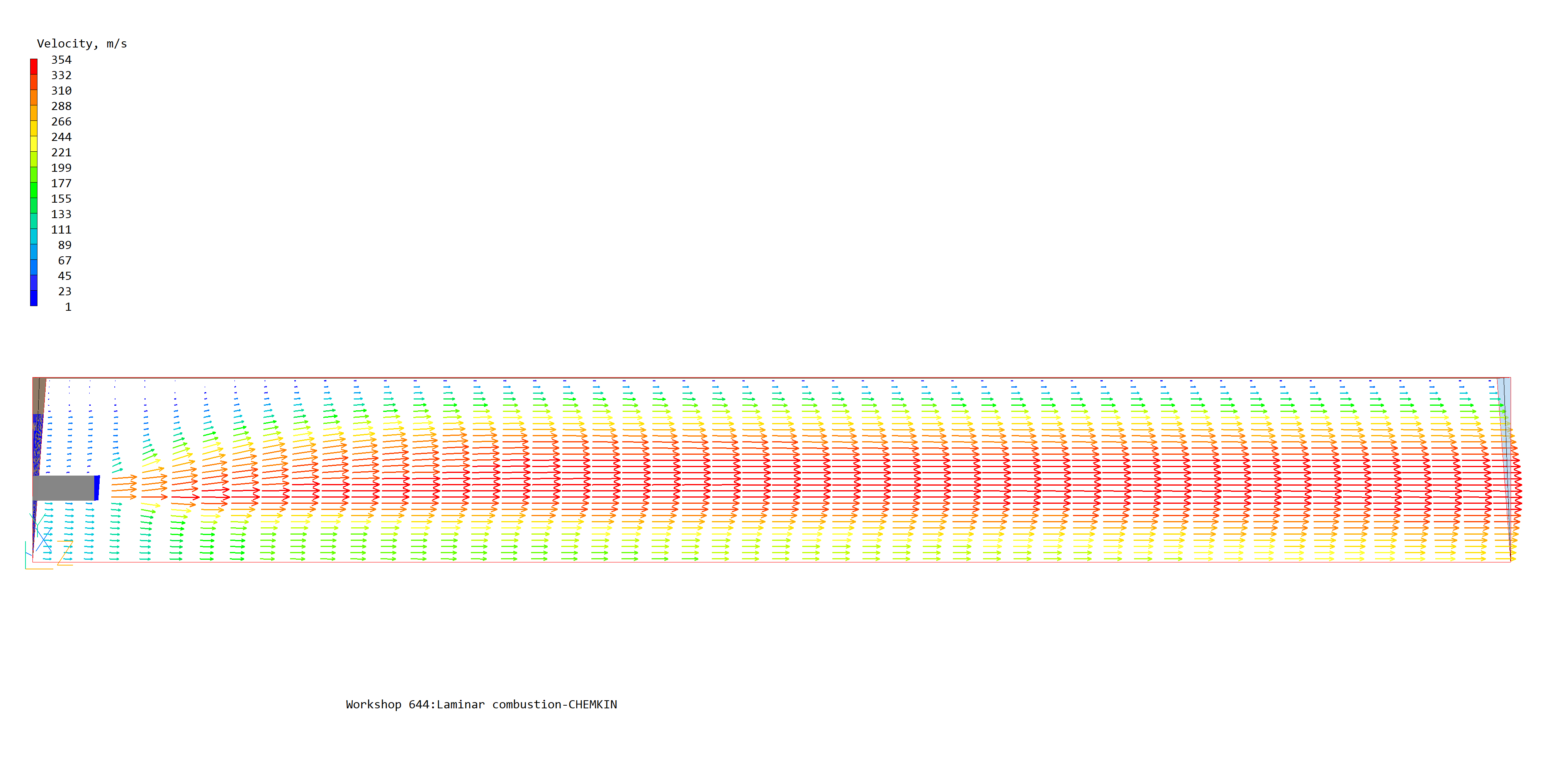
Figure 1. Velocity vectors
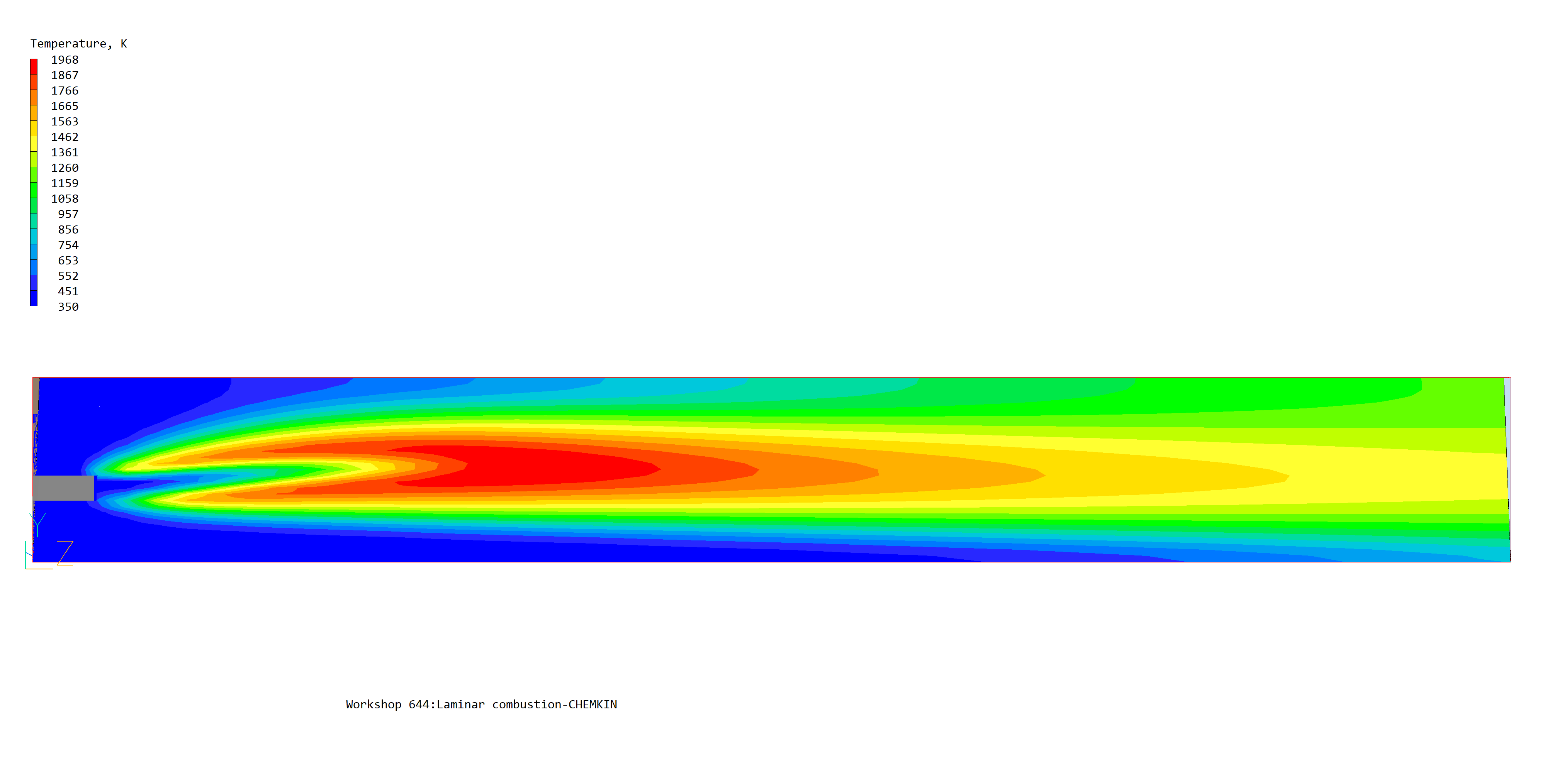
Figure 2. Temperature contours
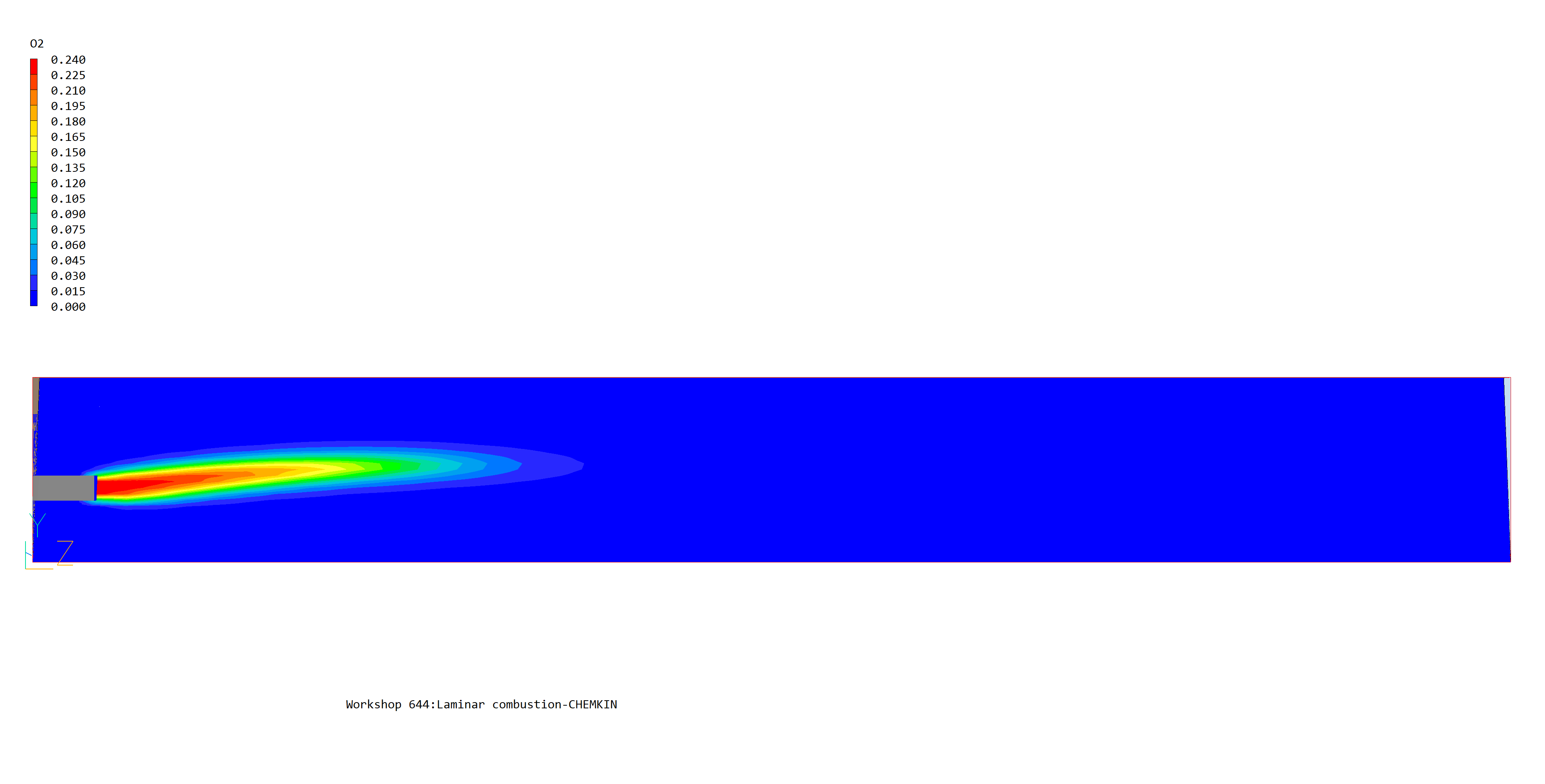
Figure 3. Oxygen (O2) contours
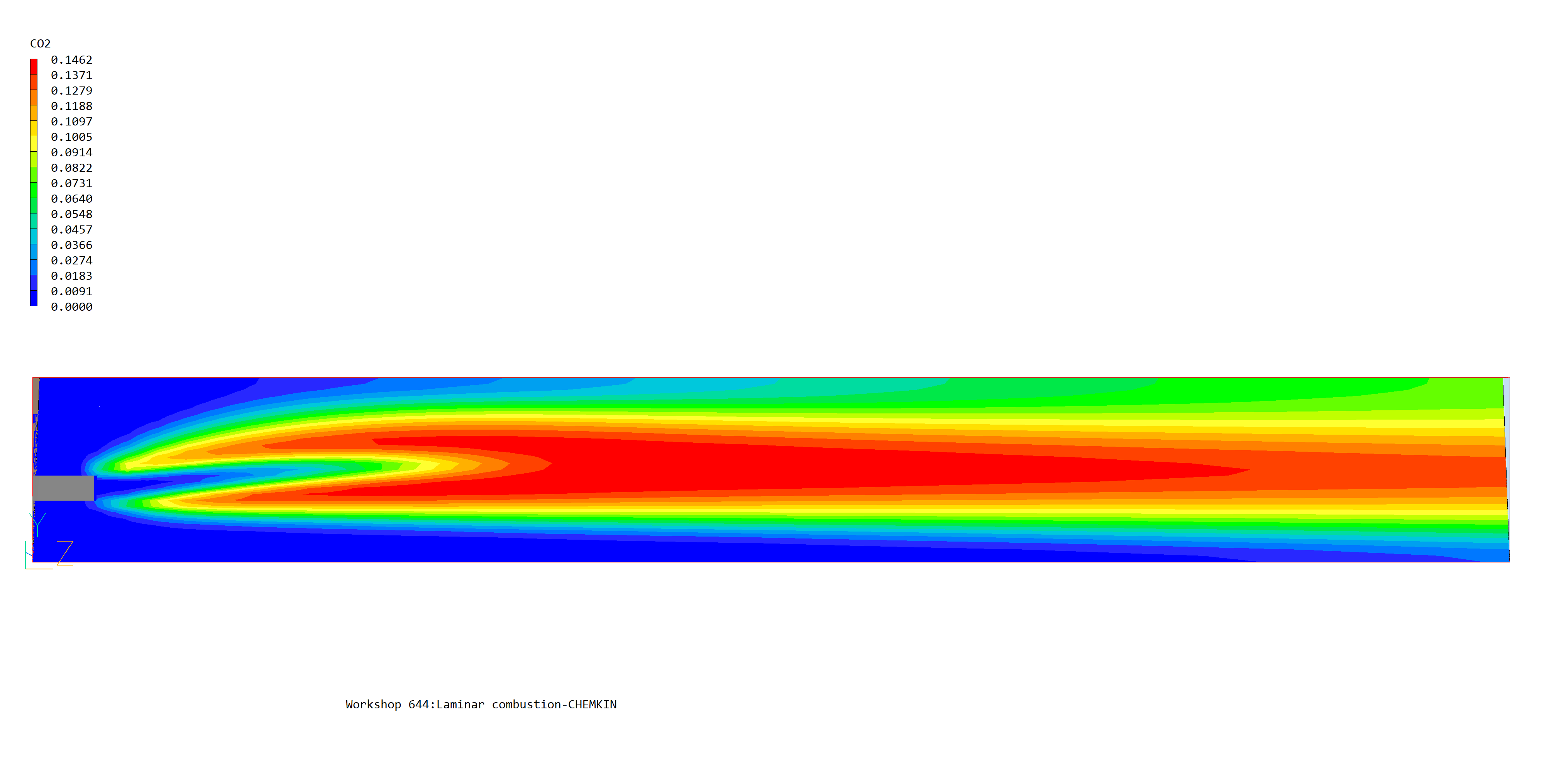
Figure 4. Carbon Dioxide (CO2) contours
In the PHOENICS-VR environment, click on 'Save as a case', make a new folder called 'COMBUST', select the new folder, and save as 'CHEMKIN'.
Further information can be found in the references cited below.
1. R.J.Kee, F.M.Rupley, J.A.Miller, 'CHEMKIN-II: A FORTRAN Chemical Kinetics Package for the Analysis of Gas-Phase Chemical Kinetics', SAND89-8009B, UC-706, Sandia National Laboratories, Albuquerque, New Mexico, (1993a).
2. R.J.Kee, G.Dixon-Lewis, J.Warnatz, M.E.Coltrin, and J.A.Miller, 'A FORTRAN Computer Code for the Evaluation of Gas-Phase Multicomponent Transport Properties", Sandia Report SAND86-8246, UC-401, (1993b).
3. R.J.Kee, F.M.Rupley and J.A.Miller, 'The CHEMKIN Thermodynamic Data Base', Sandia Report SAND87-8215B, UC-4, (1993c).
4. P.Glarborg, R.J.Kee, J.F.Grear, J.A.Miller,'PSR: A FORTRAN Program for Modelling Well-Stirred Reactors', SAND86-8209, Sandia National Laboratories, Albuquerque, New Mexico, (1992).
5. J.F.Grear, 'The Twopnt Program for Boundary Value Problems', Sandia Report SAND91-8230, (1992)