This tutorial covers the following aspects of CAD import:
Very often CAD files will contain unexpected holes, or some facets will point inwards.
When a CAD file is imported into PHOENICS, it forms a single object, even if the file contains several distinct bodies. In many cases this is perfectly acceptable, but sometimes it causes problems. If one part is made of a different material than the others, or if a boundary condition such as a heat source is to be applied to one part, this would not be possible.
The solution to the first problem is to attempt to mend the holes and make all the facets point in a consistent (outward!) direction.
The solution to the second is to split the single object back into the individual parts. If this can be done in the CAD program, this is the best option. If this is not possible, for whatever reason, the Datmaker utility can be used.
In this tutorial we will import a single STL file containing three separate objects. We will then use Datmaker to repair errors and finally to split the resulting geometry DAT file up into the three constituent parts.
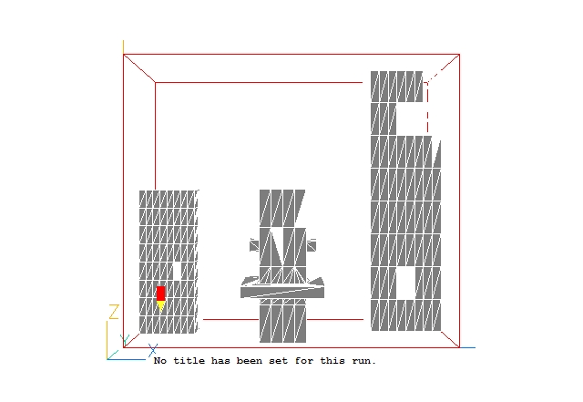
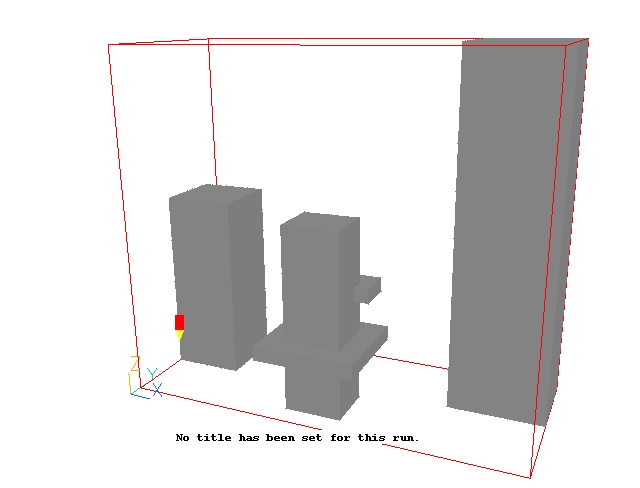
The full geometry of the case is shown in Figure 1 below.
Figure 1. The geometry of the CAD import example
The CFD solution is not of interest for this tutorial.
A complete step-by-step guide, showing how to set the case from the default mode of operation, is provided below.
From the system level:
To enter the PHOENICS-VR environment, click on the PHOENICS icon on the desktop, or click on Start, programs, PHOENICS, PHOENICS.
From the commander level:
To enter the PHOENICS-VR environment, click on the 'Run vre' icon in the left column.
In PHOENICS-VR environment,
Start with an 'empty' case - click on 'File' then on 'Start New Case', then on 'Core'', then click on 'OK'; to confirm the resetting.
To enter VR Editor:
This is the default mode of operation.
Import the STL file
Click on
on the VR-Editor panel (or the O icon on the tool bar) to bring up the Object Management Dialog; and then on 'Object', 'New', 'Import CAD Object'.
In the file browser which appears, browse to \phoenics\d_polis\d_wkshp\cadimprt, and select the file building.stl. Click 'Open'.
On the Import STL Data dialog that opens, click OK to accept the setting that the converted geometry file is to be placed in the current working directory and all other defaults. (If this were a common geometry that was to be used in many projects, it would be better to place it in the central store so that it was easily accessible). The following dialog should appear:
Change the 'No' next to 'Take size from geometry file' to 'Yes', then click 'OK'. The converted geometry file will now be read in. The size of the new object will be set to 5.5m * 2.3m * 4.8m, at 0.0, 0.0, 0.0.
Click OK to close the Object specification dialog.
On the toolbar, click the down arrow next to
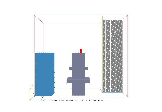
and select 'Fit to window'. The screen should look like this:
There are obvious holes in the blocks, which need to be repaired. Once these are fixed, we will want to make each block a separate object.
Repairing the errors
There are two reasons why holes may appear in the geometry:
- There may be genuine holes in the surface - facets are missing; or
- The facets are present, but point in the wrong direction.
To find out which of these is causing the problem, we can tell VR-Editor to draw all facets as double-sided, in which case we can see them from both sides. To do this, click 'View', 'Show back of objects'.
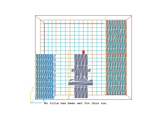
The screen should look like this:
Some of the holes have gone, but some remain. It would appear that this geometry contains both kinds of errors.
The Datmaker utility can be used to repair many common errors in geometry files and to split into closed volumes. To start Datmaker, click 'Settings', 'Datmaker operations'.
The Datmaker GUI should appear:
As the new object B1 should already be selected, the input box for 'Select first object' will contain B1. If it does not, click the down-arrow next to CHAM and select B1. This is the object to be operated on.
As we have holes and back-to-front facets, make sure 'Do Hole Mend' and 'Consistent' are both ticked, then click OK to run Datmaker.
The repaired geometry will be called 'mygeom.dat', and a copy of the Q1 containing the model in its current (pre-repair) state will be saved to 'saved.q1'. Both these names can be changed if required. The saved q1 can be used to recover the model should something go very wrong with the repair.
If 'Post operation graphics display' is ticked, Datmaker will display the repaired geometry, but this is not usually required by users.
The screen should now look like:
To make sure that everything is correct, click 'View', 'Show back of objects' again to turn off double-sided facet drawing. The image should remain the same. Rotate the image to look at it from all directions, and check that there are no holes.
Splitting into parts
We will now use Datmaker again, this time to split the geometry up into its constituent parts. Click 'Settings', 'Datmaker operations'.
- Make sure B1 is set as the first object.
- Un-tick 'Do Hole Mend' and 'Consistent', as these operations have already been performed.
- Tick 'Object changes', and select 'Split'.
- Click OK to perform the operation.
The screen should now look like:
Three new objects have appeared, one for each of the parts (B1_2 - B1_4). Note that all of them have been set to not affect the grid, and B1 has been changed from a BLOCKAGE to a NULL object. This guarantees that the mesh will not have been changed as a result of splitting the shape.
Checking for Detection Problems
Having imported the geometry, it is worth checking to see if it will be detected properly by the Earth solver. Do do this, we need to set a mesh and perform 2 or 3 sweeps (iterations).
In the object management dialog, select B1_2, B1_3 and B1_5. Click the right mouse button, and select 'Object affects grid','In all directions'.
Click on the Mesh toggle
on the hand-set or toolbar. The default grid should look like this:
Click on the Mesh toggle to turn off the mesh display.
Click on
on the hand-set or M on the toolbar to bring up the main Menu. Go to the Numerics page. Change the 'Total number of iterations' to 2, then Top Menu, OK to close the Main Menu.
Click 'Run' 'Solver' to make the Earth run.
Once the Solver run has finished, enter the VR-Viewer to examine the solution (Click 'Run' - 'Post processor' ,'GUI ').
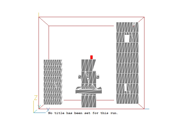
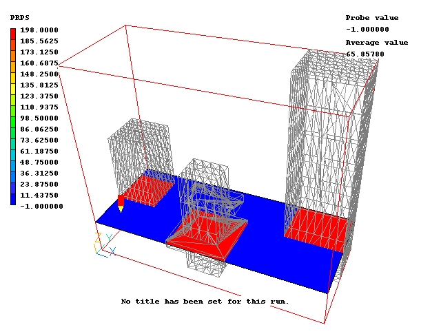
In the Viewer, switch the plotting plane to Z (click Z on the handset or toolbar), and select the property-marker variable PRPS by clicking the
icon on the hand-set or toolbar, then selecting PRPS from the list of variables. Switch the contours on by ticking 'Show contours' on the Viewer Options dialog, or by clicking
on the hand-set or toolbar. The PRPS contours should be blue in the airspace, and red inside the buildings.
To see inside the objects, go to wireframe mode by clicking
on the hand-set or toolbar.
Moving the probe up to around 0.9m, we can see that the objects are detected quite well.
By moving the probe up and down in Z, and also scanning through the X and Y planes you can get a feel for how well the shapes have been picked up.
You can increase the number of cells used and re-check the detection.
In the PHOENICS-VR environment, click on 'Save as a case', make a new folder called 'CAD', select the new folder, and save as 'SPLIT'.