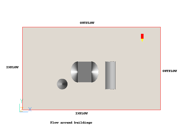
The following instructions will allow the user to set up and run the simulation of an external flow around three buildings created with some current objects in PHOENICS VR Editor.
The case is three-dimensional and its geometry is shown below. The wind velocity profiles at the inlet boundaries and the exits are set using a WIND object.

The wind speed is 10m/s from the South-West at a reference height of 10m. The domain is oriented with the Y axis pointing due North and Z pointing up. The wind profile is logarithmic, and the upstream roughness height is 0.03m, which is typical for open flat terrain.
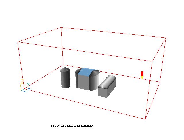
The calculations are performed using the PHOENICS solver, EARTH, and the results are viewed using VR Viewer. Velocity and pressure will be simulated. Turbulence is represented using the Chen-Kim KE turbulence model.
First activate the PHOENICS Satellite module in VR-Editor mode by either:
If you are uncertain of, or wish to change, your working directory, click on 'Options', 'Change working directory'.
When the Editor starts execution, what it shows on the screen will depend on what happens to be in your working directory. You can disregard this.
In order to make a fresh start;
You are now ready to begin.
Set the domain size, and activate solution of variables:
Click on 'Main Menu' and then on 'Geometry'.
Change the X-Domain Size to 200 m.
Change the Y-Domain Size to 120 m.
Change the Z-Domain Size to 80 m.
Click OK to close the Grid mesh settings dialog.
Click on 'Models'.
Leave the 'Solution for velocities and pressure' as ON. The default Chen-Kim KE turbulence model can also be left.
Click on 'Top menu', then on 'OK'.
The domain no longer fits the screen. To resize the view so that it does fit, click on the pull-down next to the 'R' icon on the toolbar then 'Fit to Window'.
Create the objects making up the scene
Click on the 'Object Management' button (O on the toolbar or
on the hand set). This will display a (currently empty apart from the domain) list of objects.
Create the Wind object:
Click on 'Object', 'New', 'New object', 'Wind'.
Change name to WIND.
Click on 'Attributes' and set:
- Wind speed 10m/s
- Wind direction - select 'South-West' from the list. (This is equivalent to selecting 'User' and entering 225 degrees)
- Reference height 10m
- Angle between Y and North 0.0
- Profile type: Logarithmic
- Vertical direction: Z
- Effective roughness height: 0.03 m
- Include open Sky: Yes
- Include ground plane: Yes
Click on 'OK' to exit from the Object Dialogue Box.
The object will expand to fill the domain.
The WIND object, though now transparent, obscures the domain. Right-click the object and select 'Hide object'.
The WIND object will create wind_profile inflow boundaries on the low-x and low-y faces of the domain, and fixed pressure boundaries on the high-x, high-y and high-z faces. The low-z face will have a wall-boundary condition applied, using fully-rough wall functions, and the same roughness height as the wind profiles.
The domain size can now be changed if required, and the inflow, outflow and ground boundaries will automatically adjust themselves to always be at the edges. The wind direction and/or orientation of the domain can be changed, and the inflow and outflow boundaries will be adjusted accordingly.
Create body of cylindrical building:
Click on 'Object', 'New', 'New Object', 'Blockage'.
Change name to BUILD_1.
Set POSITION and SIZE of object as:
Xpos: 50 Xsize: 15
Ypos: 30 Ysize: 15
Zpos: 0 Zsize: 30
In 'Shapes' under 'Geometry', select public\Basic_Shapes\cylinder.
The default object type is Blockage, with default attribute 'solid with smooth-wall friction. This is good for this case, so we don't need to change any attributes.
Click on 'OK' to exit from the Object Dialogue Box.
Create conical roof of cylindrical building:
Click on 'Object', 'New', 'New Object', 'Blockage'.
Change name to ROOF_1.
Set POSITION and SIZE of object as:
Xpos: 50 Xsize: 15
Ypos: 30 Ysize: 15
Zpos: 30 Zsize: 5
In 'Shapes' under 'Geometry', select public\Basic_Shapes\cone.
Click on 'OK' to exit from the Object Dialogue Box.
Create core of body of central building:
Click on 'Object', 'New', 'New Object', 'Blockage'.
Change name to BUILD_21.
Set POSITION and SIZE of object as:
Xpos: 80 Xsize: 20
Ypos: 40 Ysize: 30
Zpos: 0 Zsize: 25
Click on 'OK' to exit from the Object Dialogue Box.
Create half-cylindrical left end of central building:
Click on 'Object', 'New', 'New Object', 'Blockage'.
Change name to BUILD_22.
Set POSITION and SIZE of object as:
Xpos: 70 Xsize: 10
Ypos: 40 Ysize: 30
Zpos: 0 Zsize: 25
In 'Shapes' under 'Geometry', select public\Basic_Shapes\half-cylinder. The new shape is not aligned correctly. Click on 'Options' then 'Rotation options'. The 'Rotate object face' entry sets the orientation of the shape with its bounding box. There are 24 possible orientations. Keep changing the orientation number until you find the one which makes the shape lie correctly (it is number 2). An alternative way to do the same job is to repeatedly click on the 'Rotate object up/down' buttons
on the handset (if it is visible).
Click on 'OK' to exit the Rotation Options menu,
Click on 'OK' to exit from the Object Dialogue Box.
Create half-cylindrical right end of central building:
Click on 'Object', 'New', 'New Object', 'Blockage'.
Change name to BUILD_23.
Set POSITION and SIZE of object as:
Xpos: 100 Xsize: 10
Ypos: 40 Ysize: 30
Zpos: 0 Zsize: 25
In 'Geometry', select public\Basic_Shapes\half-cylinder .
Turn the shape to the right position as before. (rotation 4/24).
Click on 'OK' to exit from the Object Dialogue Box.
Create half-cone left end of roof of central building:
Click on 'Object', 'New', 'New Object', 'Blockage'.
Change name to ROOF_21.
Set POSITION and SIZE of object as:
Xpos: 70 Xsize: 10
Ypos: 40 Ysize: 30
Zpos: 25 Zsize: 5
In 'Geometry', select public\Basic_Shapes\half-cone.
Turn the shape to the right position as before. (rotation 2/24).
Click on 'OK' to exit from the Object Dialogue Box.
Create half-cone right end of roof of central building:
Click on 'Object', 'New', 'New Object', 'Blockage'.
Change name to ROOF_22.
Set POSITION and SIZE of object as:
Xpos: 100 Xsize: 10
Ypos: 40 Ysize: 30
Zpos: 25 Zsize: 5
In 'Geometry', select public\Basic_Shapes\half-cone.
Turn the shape to the right position as before (rotation 4/24).
Click on 'OK' to exit from the Object Dialogue Box.
Create front half of central wedge roof of central building:
Click on 'Object', 'New', 'New Object', 'Blockage'.
Change name to ROOF_23
Set POSITION and SIZE of object as:
Xpos: 80 Xsize: 20
Ypos: 40 Ysize: 15
Zpos: 25 Zsize: 5
In 'Geometry', select public\Basic_Shapes\wedge.
Turn the shape to the right position as before (rotation 3/24).
Click on 'OK' to exit from the Object Dialogue Box.
Create back half of central wedge roof of central building:
Click on 'Object', 'New', 'New Object', 'Blockage'.
Change name to ROOF_24
Set POSITION and SIZE of object as:
Xpos: 80 Xsize: 20
Ypos: 55 Ysize: 15
Zpos: 25 Zsize: 5
In 'Geometry', select public\Basic_Shapes\wedge.
Turn the shape to the right position as before (rotation 1/24).
Click on 'OK' to exit from the Object Dialogue Box.
Create body of right-hand building:
Click on 'Object', 'New', 'New Object', 'Blockage'.
Change name to BUILD_3.
Set POSITION and SIZE of object as:
Xpos: 120 Xsize: 15
Ypos: 30 Ysize: 40
Zpos: 0 Zsize: 15
Click on 'OK' to exit from the Object Dialogue Box.
Create arched roof of right-hand building:
Click on 'Object', 'New', 'New Object', 'Blockage'.
Change name to ROOF_3.
Set POSITION and SIZE of object as:
Xpos: 120 Xsize: 15
Ypos: 30 Ysize: 40
Zpos: 15 Zsize: 5
In 'Geometry', select public\Basic_Shapes\half-cylinder.
Turn the shape to the right position as before (rotation 5/24).
Click on 'OK' to exit from the Object Dialogue Box.
Set the grid:
Click on the 'Mesh toggle' button. The default mesh will appear on the screen.
The orange lines are region lines,and denote the edges of the bounding boxes of each object. The blue lines are ordinary grid lines introduced by the auto-mesher.
Click anywhere on the grid, and the 'Gridmesh settings' dialog box will appear.
The grid in all three directions is set to 'Auto'. For this case it gives approximately 54 cells in X, 52 in Y and 48 in Z. This will suffice for the tutorial, though they would not be enough for a 'real' calculation.
Click on 'OK' to exit from the Gridmesh settings dialog, and click the 'Mesh toggle' again to turn the mesh display off.
Set the remaining solution-control parameters:
Click on 'Main Menu' and then on 'Numerics'.
The default number of iterations is 1000. This is more than enough to determine whether a model has been set up correctly, but is not always enough to obtain an accurate solution.
Reset the total number of iterations to 200. More than this are required for full convergence, but 200 are enough for the purposes of the tutorial to generate a reasonable flow field.
Click on 'Initialisation'. The default initial values are 1E-10 - in effect 0. The WIND object will automatically initialise the X and Y direction velocities to an appropriate value. It will also set the initial KE and EP to the values at the domain mid-height.
Click on 'Top menu' to return to the top menu.
Click on 'OK' to exit the Main Menu.
Setting the Probe Location
Before running the solver,it is a good idea to place the probe in a suitable place to monitor the convergence of the solution. Too close to an inlet, and the value will settle down very quickly before the rest of the solution. Placed in a recirculation zone, it may still show traces of change even though the bulk solution is converged. In this case, somewhere downstream of the buildings is fine.
Click on the probe icon
on the toolbar or double-click the probe itself, and move the probe to X=175, Y=100, Z=10.
In the PHOENICS-VR environment, click on 'Run', 'Solver', and click on 'OK' to confirm running Earth.
In the PHOENICS-VR environment, click on 'Run', 'Post processor',then GUI Post processor (VR Viewer) . Click 'OK' on the file names dialog to accept the default files.
To view:
To select the plotting variable:
To change the direction of the plotting plane, set the slice direction to X, Y or Z ![]()
To change the position of the plotting plane, move the probe using the probe position buttons

Alternatively, click on the probe icon ![]() on the toolbar or
double-click the probe itself to bring up the Probe Location dialog.
on the toolbar or
double-click the probe itself to bring up the Probe Location dialog.
A typical plot from this case is:
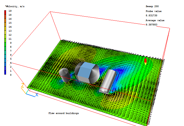
It is very important to know whether the inflows and outflows of mass and energy are in balance. If they are, it is a good sign that the solution is convergent. If they are not, the solution is definitely not converged. For further information on the assessment of Convergence, see the lecture Convergence monitoring and control.
Open the Object Management dialog, and right-click on the Domain entry. From the context menu select 'Show nett sources'. This will display the sources and sinks of all variables.
The section showing 'Nett source of R1 at...' shows the mass source in kg/s at each inlet and outlet.
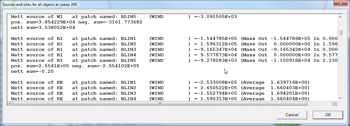
Positive values are inflows,negative values are outflows. The 'nett sum' at the end of the section should be close to zero, as all the mass entering must leave.
These balances can also be checked by inspecting the RESULT file. This contains an echo of the inputs, a selection of the solution and the source balances. Click on 'File', 'Open file for editing', then 'Result'. Scroll down the file until you reach the section headed 'Sources and sinks'.
Click on 'Save as a case', make a new folder called 'BUILDING' (e.g.) and save as 'CASE1' (e.g.).
Return to the Editor - click 'Run', 'Pre processor - GUI'.
One of the output options is to calculate the forces and moments on blockage objects, and print them to the result file. To activate this feature, open the Main Menu (in the Pre processor), then click on 'Output'. Turn 'Output of forces and moments on blockage objects' to ON.
By default, only the pressure forces are integrated over the surface of each body. To add in the friction components, we must store the friction forces. Click on 'Settings' next to the force output switch, and toggle 'Include friction force in force sum' to ON. Click 'Previous panel' to leave this page.
We do not have to repeat the whole calculation - we can restart and perform just 1 or 2 iterations to generate the extra output.
Click on 'Initialisation', and then 'Activate Restart for all variables'. Click on 'Numerics' and set the total number of iterations to 3.
Click 'Top Menu' an 'OK' to close the Main Menu.
Run the solver as before, then enter the viewer.
To see the forces on individual objects, select an object, say BUILD-1, right click and select 'Show nett sources'. The following dialog will appear:
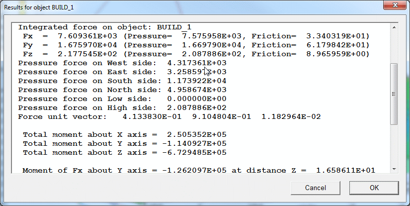
To see the forces on all the objects, bring up the Object management dialog, right-click on DOMAIN and select 'Show nett sources'. The forces and moments will be shown after the sums of sources. Alternatively click on 'File', 'Open file for editing', 'RESULT'. In the file editor, search for the string 'Integrated force', which is below the source printout..