In this tutorial you will learn about:
At the end of the tutorial you may like to confirm your understanding by the following exercises:
In BFC, as for Cartesian/polar co-ordinates, the geometry is created first, and the mesh is fitted later.
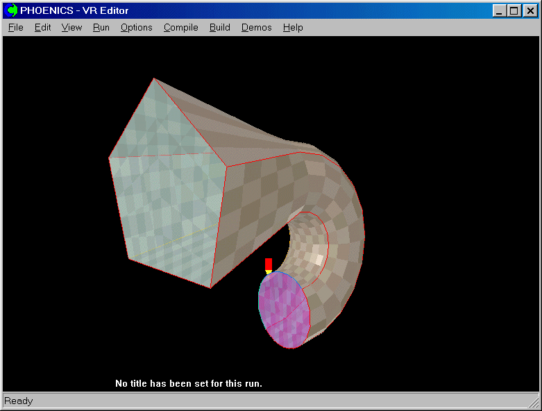
This tutorial deals with the creation of the geometry for a duct, where the cross-section changes from a pentangle to a circle along the length.

The order of the data entity generation and modification is:
This tutorial covers stage 5.
In BFC Tutorial 1, we created the geometry for the pentangle and circle, and in BFC Tutorial 2 we created the required frames.
We now continue the process of meshing by fitting a grid into the frames.
From the system level:
To enter the PHOENICS-VR environment, click on the PHOENICS icon on the desktop, or click on Start, programs, PHOENICS, PHOENICS.
From the commander level:
To enter the PHOENICS-VR environment, click on the 'Run vre' icon in the left column.
In PHOENICS-VR environment,
Start with Library case B112 - click on 'File' then on 'Load from libraries'. Type B112 into the Case Number box, then click OK.
To enter VR Editor:
This is the default mode of operation.
Activate the Grid Generator by clicking on the Grid mesh toggle on the hand-set ![]() , then clicking anywhere within the domain to bring up the BFC menu dialog.
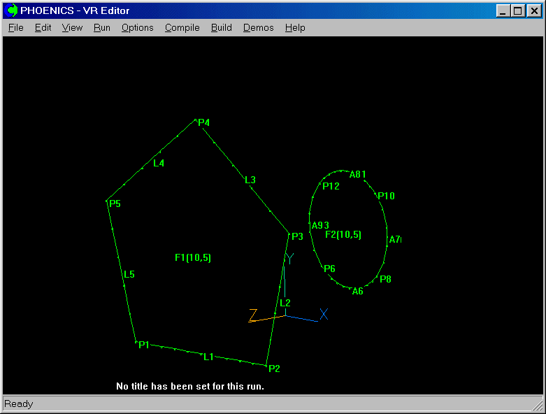
The grid generator screen is shown below:
, then clicking anywhere within the domain to bring up the BFC menu dialog.
The grid generator screen is shown below:
If you are continuing BFC Tutorial 2, you will join Tutorial 3 here.
The grid directions are known as I, J and K. There is no link between these, and the Cartesian axes X Y & Z used for geometry definition.
It is up to you to decide how to align the frame edges with the I/J/K grid directions, bearing in mind that both Cartesian AND grid co-ordinates must be right-handed.
We have created two frames, each having 10*5 cells. The 10 cells are to be in the I direction, and the 5 in J. There will be 5 cells in the K direction, smoothly joining the two frames. The pentangle will be at the outlet, on plane K=16.
Once the duct becomes circular at frame F2 on plane K=11, it is to rotate through 180 degrees, centred on the X axis. This section will contain a further 10 cells in K, making 15 in all.
You must specify how many computational cells are present in each direction. For this case, it is 10*5*15.
In general, there will be many frames on each plane. The number of cells is the sum of the cells on the frame edges in each direction.
Click on the 'Dimension' button. A dialog appears which allows the selection and setting for each direction in turn.
Set the number of cells in I (NX) to 10, in J (NY) to 5 and in K (NZ) to 15.
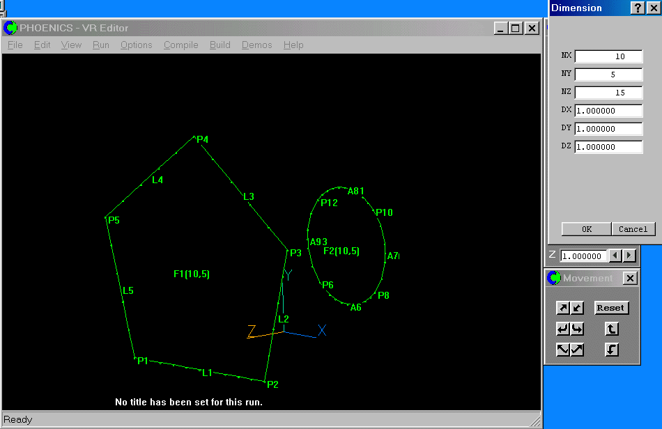
Initially, the cells are distributed evenly over a default cube. The cube size is set via the DX, DY and DZ buttons, and by default all three are '1.0'.
When all actions in this sub-menu are completed, click the 'Ok' button to return to the calling menu. The default mesh is set. It can be viewed by clicking 'Display', 'Mesh display', 'Outer mesh' , and turning the edge displays for East, North and High to 'On'. Having seen the default mesh, turn the edged display back to 'Off'. Click 'OK' to close dialogs until the BFC Menu.
We now have to match the FIRST corner of each frame to I, J and K locations. We must also specify the grid directions along the first two edges.
Click on 'Surfaces', then the 'match Grid' button, then click on the label of frame F1. The frame-matching dialog will appear:
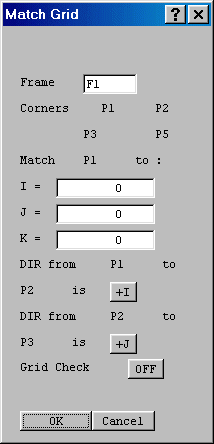
Match point P1 to I = 1, J = 1 and K = 16, the last K plane.
The direction from P1 to P2 is along +I, and from P2 to P3 is along +J, so no change is needed.
The 'grid check' button switches on a visual orthogonality checker, which shades the cells from red (ok) to blue (bad).
We are not going to use the grid checking option, so click 'Ok' to end and apply the values specified in this panel.
Once matched, the mesh is shown on the frame, and the Smoothing dialog is displayed.
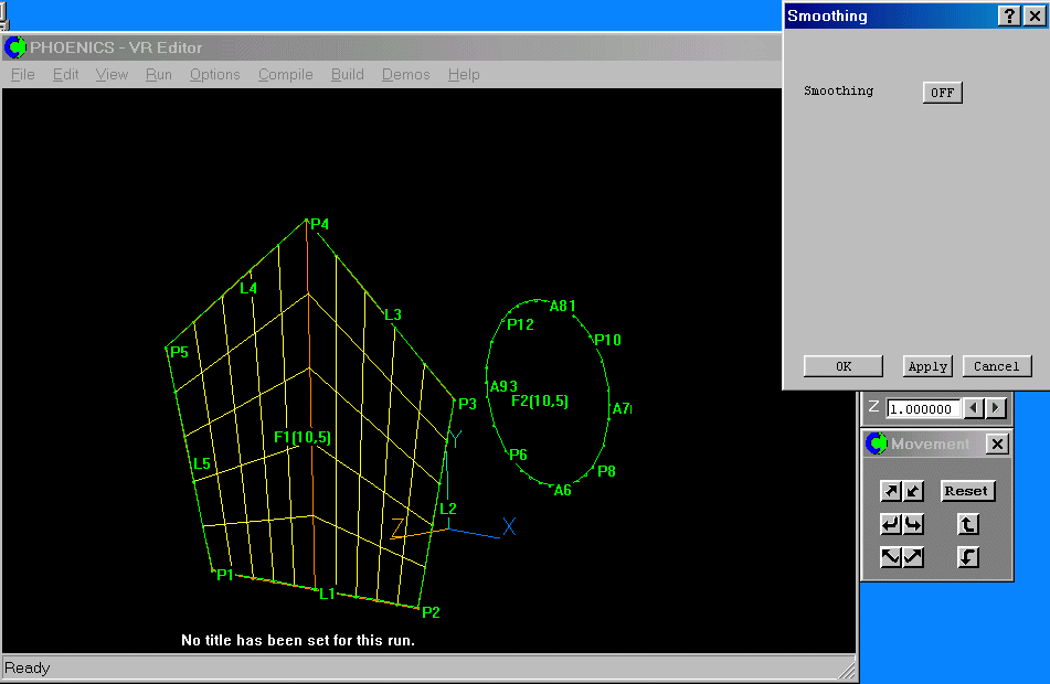
Note the red line drawn from point P4. This is a Region boundary, similar to the regions formed at object edges in the Cartesian system. Region boundaries are formed on all frame edges, and at intermediate edge points, such as P4.
We are not going to use the smoothing option for this frame, so click 'Ok' to end.
We now have to match frame 'F2'. Select it with the mouse. Match frame F2 to I=1, J=1 and K=11 (i.e. the end of the tenth cell in K).
The frame edges are curved, so turn the grid check on to see the mesh orthogonality.
Set the frame by pressing OK.
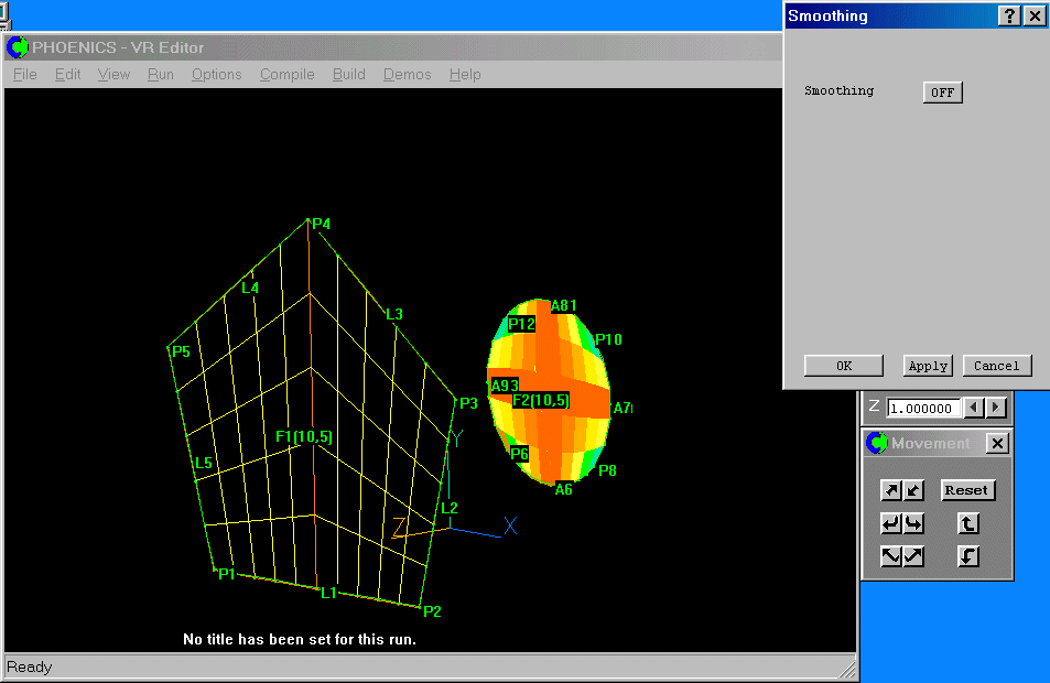
The mesh is quite poor - the 'corners' are blue/green. This could give problems with convergence. Turn the Smoothing 'On'. The dialog will change:
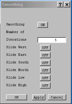
The 'Iterations' set to 5 activates a Laplace-like solver, which acts to smooth the mesh on this frame. Values between 5 & 10 usually suffice. A value of 0 means that a transfinite (linear) mapping will be used (equivalent to Smoothing Off).
The Slide West/East/South/North/Low/High buttons allow the grid to 'slide' along the frame boundaries. If the frame boundary does not align with one of the Cartesian axes, the results may be unpredictable!
Set the number of iterations to 10. Click 'Apply' to see the effect of the smoothing:
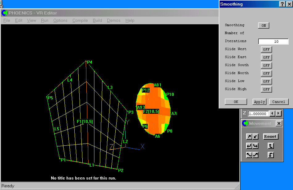
The grid is now much better - the blue has gone. We can still improve it some more by pushing the cells towards the corners of the frame. Click on 'OK' to close the Smoothing dialog, then again to close the Grid matching dialog.
Click on the 'Lines' button, then on 'Modify line'. Select one of the arcs - A6. Set the power to S1.3. This will distribute the cells along the line symmetrically, using a power law of 1.3. Press OK to set the line.
Now do the rest of the arcs. The mesh is now much more orthogonal.
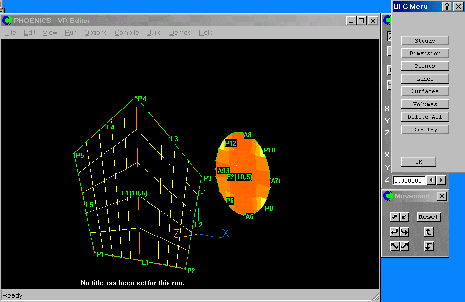
The frames for the duct have now been matched. The next tutorial shows how the geometry is completed.
If you want to proceed directly to the next tutorial, click here.
To summarise, in this Tutorial you have learned how to:
We now suggest you practice each of these functions 'live' for yourself with the following exercises:
To leave the BFC Menu, click 'OK'. To save the work so far, click on 'File', 'Save as a case', make a new folder called 'BFC ' (e.g.), and save as 'BFC3'.
Note that at this point the mesh has only been created on planes K=11 and K=16, so the VR-Editor will display a distorted default cube!