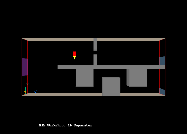
This example shows how to set up a case using ASM in VR-Editor. The case calculates the accumulation of two groups of particles, of the same density but different diameters. The geometry of the case is shown in Figure 1 below. The inlet is on the left (blue) and two outlets are on the right (grey). The fluid flows, through complicated blockages, from low-x to high-x and the slip velocity is normal to the primary flow direction.

Figure 1. The geometry of the ASM example
A complete step-by-step guide, showing how to set the case from the default mode of operation, is provided below.
From the commander level:
To enter the PHOENICS-VR environment, click on the 'Run vre' icon in the left column.
From the system level:
To enter the PHOENICS-VR environment, click on the PHOENICS icon on the desktop, or click on Start, programs, PHOENICS, PHOENICS.
In PHOENICS-VR environment,
Start with an 'empty' case - click on 'File' then on 'Start New Case', then on 'Core'', then click on 'OK'; to confirm the resetting.
To enter VR Editor:
This is the default mode of operation.
Set the domain size and grid numbers:
Click on 'Menu' (Main Menu) on the VRE-Editor panel; and then on 'Geometry'.
Change the x-domain size to 8.0.
Change the y-domain size to 3.2.
Leave the z-domain size at 1.0.
Set 'number of cells' to 40 in the x-direction, 25 in the y-direction and 1 in the z-direction.
Click on 'OK' to close the Grid mesh settings dialog.
Models settings
Click on 'Models'.
Turn 'Solution for velocities and pressure' to ON.
Click on LAMINAR (Turbulence models) and choose the KEMODL.
Click on ONE_PHASE next to 'The simulation is', and select 'Algebraic slip'.
Click 'Settings' next to ALGEBRAIC_SLIP, and set:
Number of particles: 2 then click 'Apply'.
Carrier fluid properties:
Density: 1000. ; Kinematic viscosity: 1.E-6
Particle properties:
PT1 PT2 Density: 1250 1250 Diameter: 1.E-3 1.E-4 Viscosity: 2.5E-6 2.5E-6 The user is advised to check 'Properties' which should show the same settings as above.
Initialisation
Click on 'Initialisation'. Set the initial value for PT0 to 1.0, and to 0.01 for PT1 and PT2. PT0 is the carrier fluid, and the domain is initially full of the carrier fluid with no particles. Click on > next to 'Variable' to scroll the list of variables until PT0 is visible.
Set gravitational force
Click on 'Sources'.
Switch Gravitational forces to ON. The buoyancy model is DENSITY_DIFFERENCE and gravitational acceleration is in Y-direction.
Enter numerical settings
Click on 'Numerics'.
Set 'Total of number of iterations' to 250
Set 'Global convergence criterion' to 0.0001, otherwise the pressure-correction and particle solutions may cut out too soon in this case.
Click 'Relaxation control' and set the following values:
U1 V1 KE EP PT0 PT1 0.2 0.2 -0.5 -0.3 -0.8 -0.8 Click 'Previous panel'
Click on 'Top menu' and then on 'OK' to exit from 'Menu'.
To get the right view point, click on 'Reset', then View +Z, Up +Y, then 'Fit to window'.
Create Objects and specify boundary conditions
Create the inlet
Click on 'Obj' Button on the VR-Editor control panel.
Change name to IN.
Set Position and Size of the object as:
Xpos: 0.0 Xsize: 0.0
Ypos: 1.1 Ysize: 1.0
Zpos: 0.0 Zsize: 1.0
Define Type: Inlet.
Click on 'Attributes'.
Set the Volume fraction of PT1 to 0.01
Set the Volume fraction of PT2 to 0.01
Set the X-direction velocity to 3 m/s
Click 'OK' to exit from the Object Dialogue Box.
Create the outlets
Click on 'Obj' Button on the VR-Editor control panel.
Change name to OUTU.
Set Position and Size of the object as:
Xpos: 8.0 Xsize: 0.0
Ypos: 1.7 Ysize: 0.5
Zpos: 0.0 Zsize: 1.0
Define Type: Outlet
Click 'OK' to exit from the Object Dialogue Box.
Click on 'Obj' Button on the VR-Editor control panel.
Change name to OUTL.
Set Position and Size of the object as:
Xpos: 8.0 Xsize: 0.0
Ypos: 0.0 Ysize: 0.5
Zpos: 0.0 Zsize: 1.0
Define Type: Outlet
Click 'OK' to exit from the Object Dialogue Box.
Create the blockages
Create the following 'Blockage' type objects:
Name Xpos Ypos Zpos Xsize Ysize Zsize PLT 2.0 1.5 0.0 6.0 0.2 1.0 SLTU 4.0 2.6 0.0 0.2 0.6 1.0 SLTL 4.0 1.7 0.0 0.2 0.6 1.0 BLK1 3.0 0.5 0.0 1.0 1.0 1.0 BLK2 4.5 0.0 0.0 1.0 1.0 1.0 BLK3 6.0 0.5 0.0 1.0 1.0 1.0
Create the walls
Create the following 'PLATE' type objects:
Name Xpos Ypos Zpos Xsize Ysize Zsize UWALL 0.0 3.2 0.0 8.0 0.0 1.0 LWALL 0.0 0.0 0.0 8.0 0.0 1.0
All settings are now complete. The user should move the probe (small red pencil sign) to the position shown in Figure 1 (roughly X=3.0, Y=2.0) before running the Solver, EARTH.
In the PHOENICS-VR environment, click on 'Run', 'Solver' then 'Local solver(Earth)', and click on 'OK'; to confirm running Earth.
In the PHOENICS-VR environment, click on 'Run', 'Post processor',then GUI Post processor (VR Viewer) Viewer)'. Click 'OK' on the file names dialog to accept the default files.
To view:
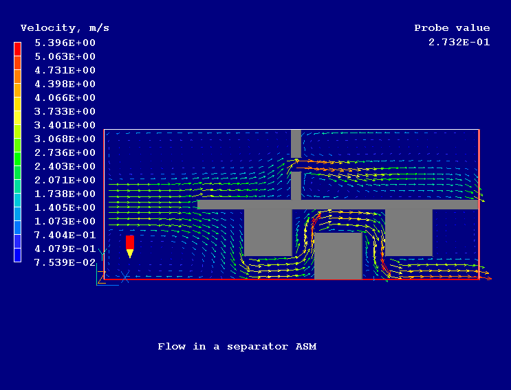
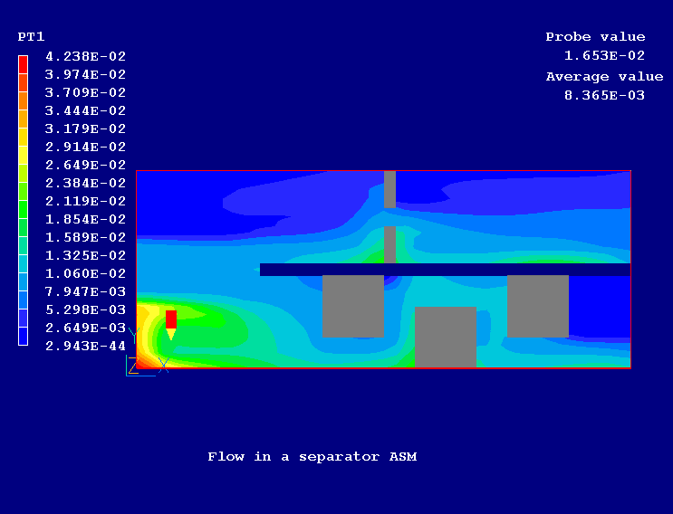
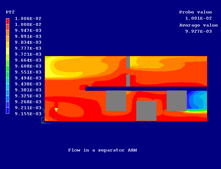
Figure 2 shows the velocity vectors and Figure 3 and Figure 4 show the distribution of particle group 1 (large diameter) and particle group 2 (small diameter) respectively.

Figure 2. Velocity vectors

Figure 3. The distribution of particle group 1

Figure 4. The distribution of particle group 2
In the PHOENICS-VR environment, click on 'Save as a case', make a new folder called 'MULTIPHS', select the new folder, and save as 'ASM'.