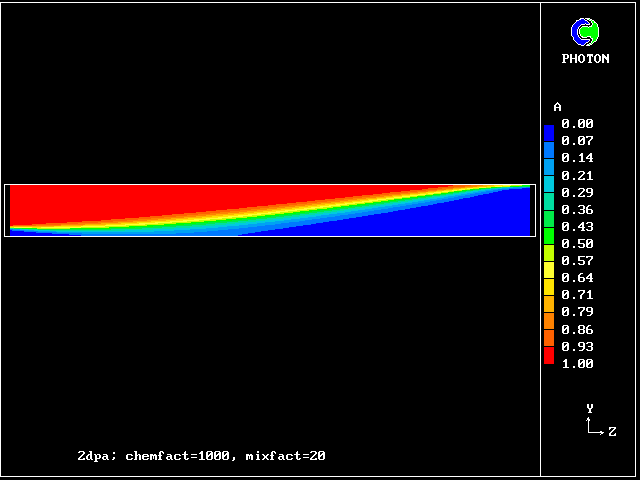
 Concentration contours of unburned fluid A,
showing the wedge-shaped flame.
                                           |
At any location, the gas        mass   |   ^unburned
mixture is supposed to          fraction   |                 ^burned
comprise A (fully-unburned),    of the |   |  part-burned    |
D (fully-burned) and B and C    two    |   |     ^           |
part-burned, distributed        gases  |   |     |           |
in accordance with laws of             |   |     | part-burned
convection, diffusion and              |   |     |     ^     |
source/sink interactions.              |   |A    |B    |C    |D
                                       |___|_____|_____|_____|_____
The latter represent transformations       0  reactedness-> 1
A + D > B; A + D > C; B + D > C; A + C > B
at rates proportional to the local mean-flow shear rate.
Also C is both hot and unreacted enough to provide: C > D.
The first application of the 4-fluid model to a combustion process concerned the steady confined flame mentioned above.
The Prandtl mixing-length model of turbulence was employed for the hydrodynamics. This demonstrates, incidentally that one need not use the multi-fluid concept for all aspects of a phenomenon.
The following colour pictures show the results, which agree qualitatively and quantitatively with the Williams, Hottel, Scurlock data.
The flow is from the left, where the flame-holder is situated, to right. Only half the duct is shown, the symmetry axis being at the bottom of the picture.
Varying the reaction-rate constant (see the referenced paper) shows and explains how it comes about that the flame-spread angle is little influenced by its reduction until a sudden extinction occurs.
 Concentration contours of unburned fluid A,
showing the wedge-shaped flame.
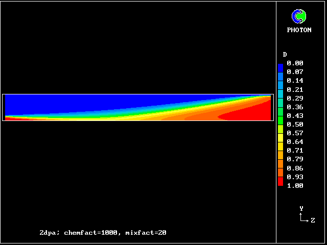 Concentration contours of fully-burned fluid D
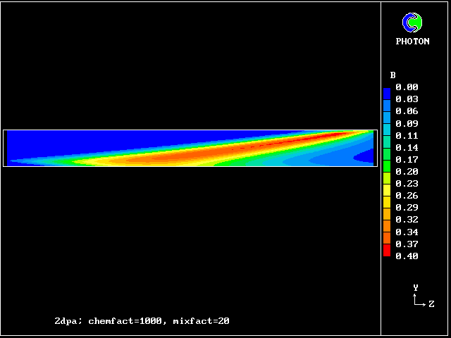 Concentration contours of partially-burned fluid,
which is too cool to burn
The comparatively low concentration of fluid C should be noted. It signifies that the reaction rate is high.
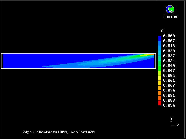 Concentration of fluid C,
which is hot enough to burn.
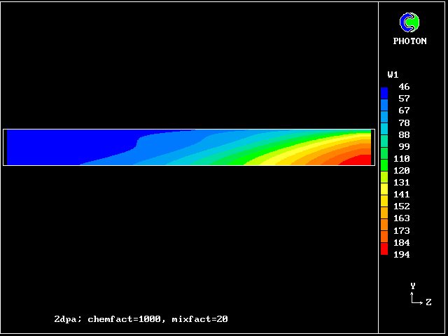 The longitudinal velocity distribution,
showing the acceleration brought about by the increase of specific
volume and the confinement within the duct walls
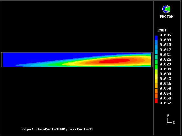 The effective viscosity, which has been deduced from the
Prandtl mixing-length model of turbulence.
Its increase down the duct results from the increasing velocity gradient.
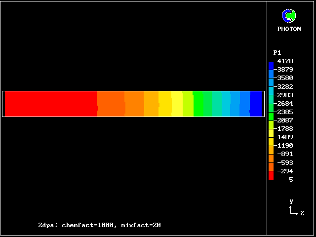 The associated pressure distribution, necessary to accelerate
the gas
It concerns a duct filled with combustible gas which is ignited at the closed end. Flame spreads to the open end, causing a pressure rise in the duct.
The duct is partially blocked by transverse baffles in order to simulate the obstructions by solid objects which, by causing recirculations in their wakes, accelerate flames in confined spaces.
   wall__________________________________________________
 closed|       |      |      |      |      |      |     | open
    end| ignition                                         end
  axis |* --- - --- - --- - --- - --- - --- - --- - --- -
Comparisons with measurement, not provided here, show good agreement.
The 4-fluid model applied to unsteady flame propagation along a duct containing transverse baffles.
 Contours of flame-arrival time
Note that the flame arrives last at a location not far from the ignition point. This is because the turbulence level is lowest there.
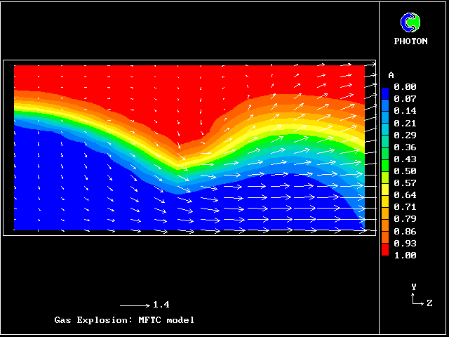 Concentrations of fully-unburned gas at a particular time,
and near a particular baffle
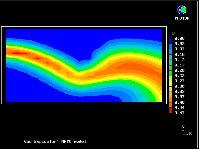 Concentrations of partially-burned gas B, at the same time,
and near the same baffle
 Concentrations of partially-burned gas C, at the same time,
and near the same baffle
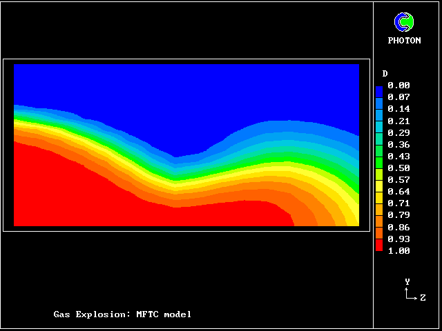 Concentrations of partially-burned gas D, at the same time,
and near the same baffle
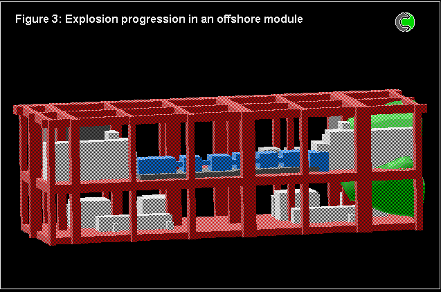
The 4-fluid model has also been used for numerous calculations concerned with full-scale models of off-shore oil platforms.
The problem is of course three-dimensional, transient, and complicated by a highly-obstructed space.
Comparisons were made with experiments, and with the predictions made by specialist computer codes having been subjected to "hindsight tuning".
The predictions based on the 4-fluid model were in at least as good agreement as those of the other codes; but there were uncertainties about the experimental conditions, as well as about the model constants.
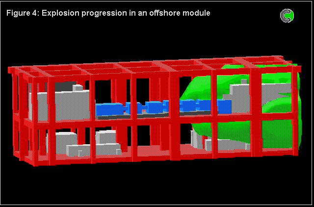
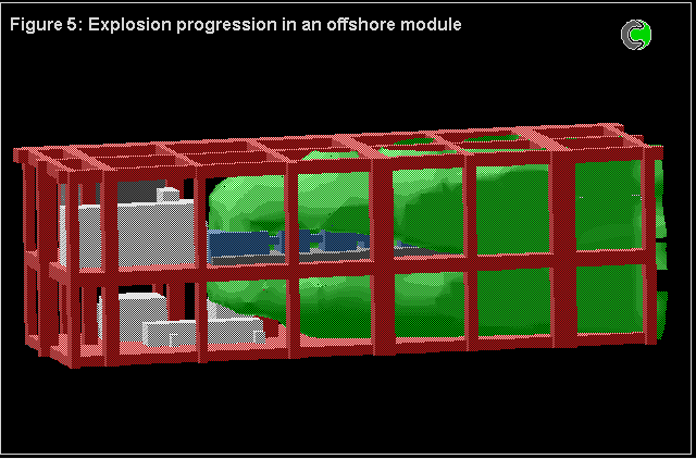
The following pictures show some results.
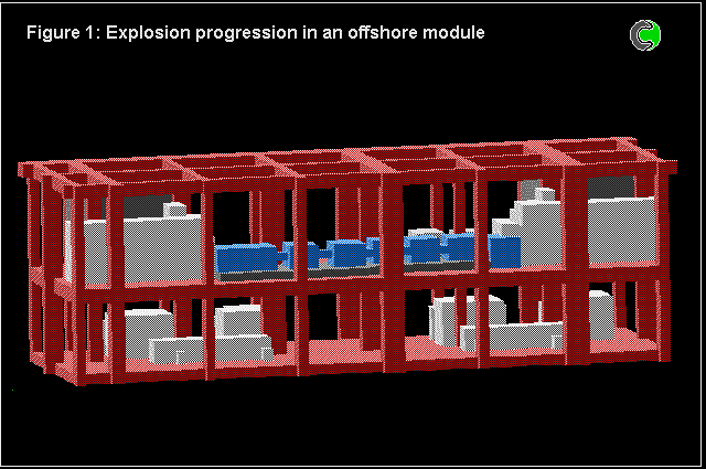 Before the start of ignition
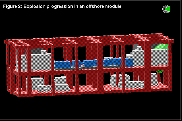 The flame, coloured green,
has been ignited at the right-hand end
 The flame is spreading to the left
 The flame spread continues
 The flame has nearly filled the whole module
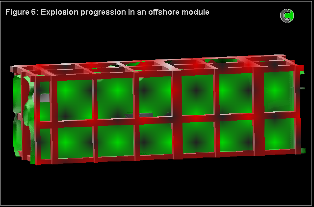 All the combustible gas in the module has now been consumed
--- end of section 5 ---