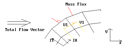
The basic principles for prescription of inlet boundary conditions for a BFC calculation are the same as for regular coordinate systems.
However, special care must be taken in defining the MASS INFLOW RATE and the VELOCITY RESOLUTES to be convected into the domain.
The MASS INFLOW RATE PER UNIT AREA across a cell boundary is simply the density times the velocity component normal to the inlet surface area.
The incoming values of the VELOCITY RESOLUTES are simply projections of the incoming velocity vector into the directions of the resolutes at the INTERIOR velocity locations of the boundary grid cell.
For a CARTESIAN grid a single velocity triangle is required.
For a BFC grid DIFFERENT velocity triangles are required for the mass flow rate and for each velocity component.
In general the required angles will vary from cell to cell. Subroutine GXBFC has been provided to calculate the inlet conditions automatically, for the case of uniform inflow.
GXBFC is called from Group 13 of GREX3, when the first three characters of the PATCH name are 'BFC'. The direction and magnitude of the external velocity vector is specified by means of COVALs for the Cartesian resolutes of this vector.
If the density is constant, or if RHO1 is not STOREd, the PIL variable BFCA is used to carry the incoming density from the satellite to GXBFC.
If the density is variable, AND the density is STOREd in Q1, the density at each inlet can be specified by means of a COVAL for RHO1.
In a two-phase case, BFCA/COVAL(...,RHO1,...) carry the first-phase (density* volume fraction) product. The second-phase values are carried by RSG28/COVAL(...,RHO2,...).
The use of COVALs for UCRT, VCRT, WCRT and density is non-standard, and simply provides a mechanism for transmission of UIN, VIN, WIN and RHOIN to GXBFC.
The following PIL commands illustrate this option for a north boundary:
PATCH (BFCIN, NORTH, 1, NX, NY, NY, 1, NZ, 1, 1) COVAL (BFCIN, P1, FIXFLU, GRND1) COVAL (BFCIN, U1, ONLYMS, GRND1) COVAL (BFCIN, V1, ONLYMS, GRND1) COVAL (BFCIN, W1, ONLYMS, GRND1) COVAL (BFCIN, UCRT, ZERO, UIN) COVAL (BFCIN, VCRT, ZERO, VIN) COVAL (BFCIN, WCRT, ZERO, WIN) Here, UIN, VIN and WIN define the Cartesian resolutes of the external velocity vector.The density at the inlet is set as
BFCA=RHOIN
if RHO1 is not STOREd or
COVAL (BFCIN, RHO1, ZERO, RHOIN)
if it is.
PHOENICS provides two alternative methods for the performance of potential-flow simulations: the DIRECT method and the DARCY method.
The DIRECT method involves using the TERMS command for the variable PHI (i.e. the velocity potential ....) to deactivate all terms of the transport equation except the diffusion term:
TERMS (PHI, N, N, Y, N, N, N)
The resulting equation
reduces to Laplace's equation for the potential in incompressible flow, if ![]() .
.
If the whole-field linear-equation solver is invoked for PHI in the SOLUTN command, the solution for the potential can be obtained in one sweep provided LITER(...) is set sufficiently large.
On the second sweep, the velocity field may be calculated from the gradient of the potential.
PHOENICS provides for this in subroutine GXPOTV called from GREX3 when POTVEL = T. Library case 116 exemplifies the use of this method for BFC=F.
The method has been little explored for BFC=T. The Darcy method is the alternative way of solving potential flows in BFCs.
The DARCY method exploits the analogy that exists between the potential-flow equations,
and the equations that govern flow in a highly-resistive medium, i.e., Darcy's law.
where k is a resistance coefficient having units of s-1.
The similarity is exploited by solving the usual momentum and continuity equations, but with DARCY=T in the Q1 file. The resistance coefficient k is set via the real PIL variable DARCON, for which the default value is 1E4.
Setting DARCY=T causes the velocities to be solved, cuts out the convection and diffusion terms for economy, and introduces high resistances for the velocities. However, the user must also introduce the command SOLVE(P1).
It is important to remember that the velocity potential is:
The variable P1 computed and printed should thus be interpreted as ![]() .
.
Convergence of the Darcy solution is usually rapid - 10 to 20 sweeps - as the equations are linear.
It is possible to restart just the velocity fields from a Darcy solution using RESTRT(U1, V1, W1). The pressure field will take the FIINIT(P1) value, but pressure-correction will quickly get the right levels.
For a coordinate system rotating with constant angular velocity omega, the apparent body-force can be resolved into the local grid directions.
These forces are incorporated into the mathematical model as additional volumetric momentum sources.
Cases 744 (radial equilibrium test) and 747 (geostropic balance) provide examples of the use of rotating coordinates. A practical example is given by case B524 for the Mizuki impeller.
Implementation In PHOENICS
The user introduces the additional momentum sources due to rotation, as follows:
In Q1 file:
PATCH(ROTA,PHASEM,1,NX,1NY,1,NZ,1,LSTEP)
COVAL(ROTA,U1,FIXFLU,GRND)
COVAL(ROTA,V1,FIXFLU,GRND)
COVAL(ROTA,W1,FIXFLU,GRND)
When the PATCH name commences with ROTA, PHOENICS activates a call to subroutine GXROTA which is called from Group 13 of subroutine GREX3. From subroutine GXROTA, a call is made to subroutine BFCROT, wherein the resolutes of the rotation forces per unit mass are calculated.
The following settings are also required:
Here, PA and PB are two points which define the axis of rotation.
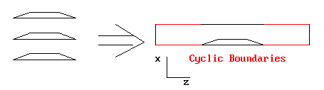
PHOENICS provides an option for applying cyclic (or periodicity) boundary conditions along the east and west boundaries of the solution domain.
The provision for BFCs is intended for turbomachine applications in which cyclic conditions are needed at the entrance to and exit from the blade passage.
The default setting in PHOENICS is no cyclic conditions, and a symmetry condition is assumed.
To activate x-cyclic boundaries, the following PIL command is inserted in Group 6 of the Q1 file:
XCYIZ(1,NZ,T) (switches XCYCLE on for all IZ slabs)
For a case where x-cyclic boundaries are required upstream and downstream of a blade cascade starting at IZ=10, and ending at IZ=20, the following commands will achieve the desired result:
XCYIZ(1,9,T) (switch XCYCLE on for IZ=1 to 9)
XCYIZ(21,NZ,T) ( " " " " IZ=24 to NZ)
Library case B523 exemplifies the use of x-cyclic boundary conditions for the case of supersonic flow through a cascade of wedges.