Introduction
SPARSOL and PARSOL are techniques used in PHOENICS to detect geometrical features which are not aligned with the cartesian or cylindrical-polar grid. The geometry of such features is created in PHOENICS-VR by either:
The task of SPARSOL and PARSOL is to determine how the facets defining the geometry intersect the grid. The facets of all the non-grid-aligned objects comprising the model are sent to EARTH by means of a FACETDAT file, which is produced by the Virtual- Reality interface of PHOENICS when preparing to run Earth.
Advantages and Disadvantages
SParsol
This is the default method for dealing with faceted objects of any shape, whether imported from CAD or using one of the supplied common shapes.
It is activated by the setting
ISG62=1; PARSOL=F
in Group 19 of Q1, or by selecting 'SPARSOL' from the 'Cut-cell method' box of the Grid Mesh Settings dialog.
Sparsol concentrates on the links between neighbour cells. It calculates the intersections of the cell-centre grid lines with the geometry and arranges that the distance from the node to the wall on either side is correct. The cell areas are also adjusted
Advantages
- It is fast and usually reliable
- It handles conjugate heat transfer well, including Immersol or P1-T3 radiation models
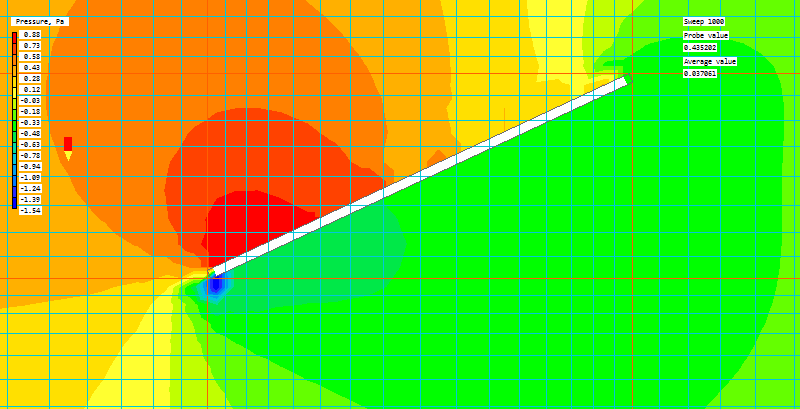
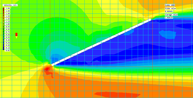
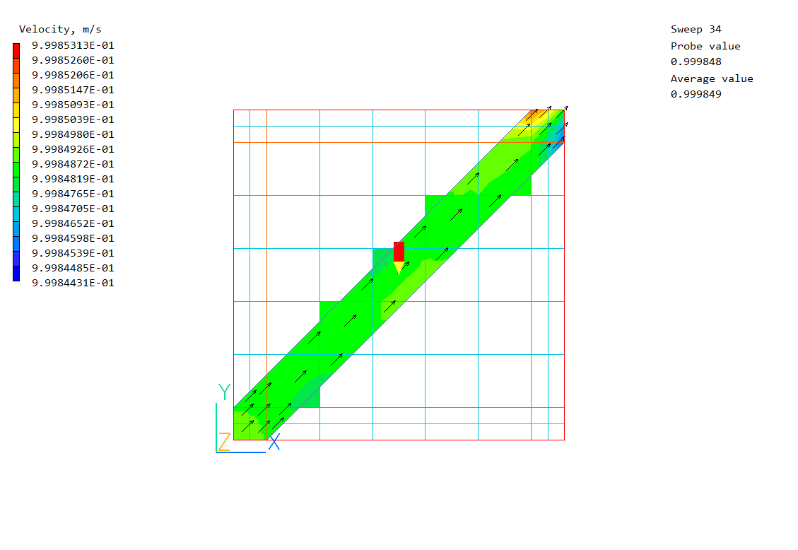
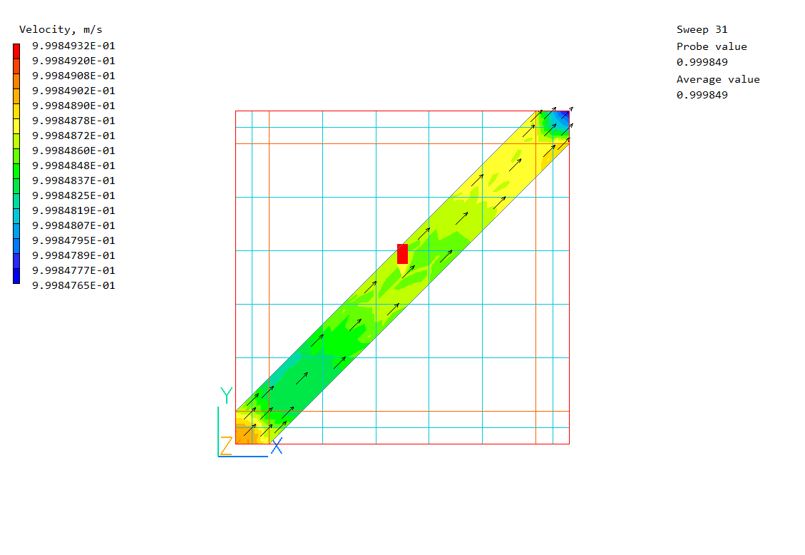
- It can detect and handle objects thinner than the current cell, as shown in the next two images (flow left to right):
Disadvantages
- As there are no true cut cells, the representation of curved surfaces in the hydrodynamics is simple.
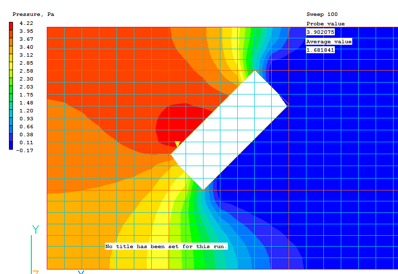
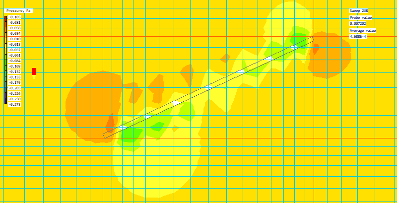
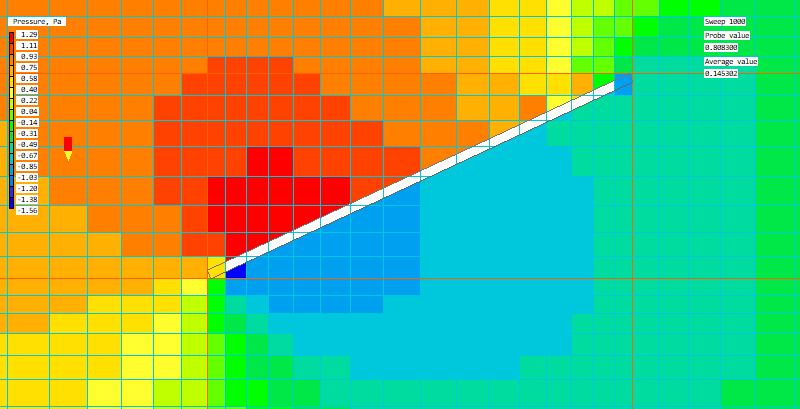
The first image shows pressure contours with contour averaging turned on. The Viewer is displaying the true geometry:
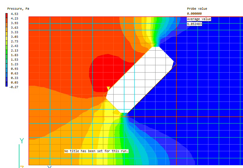
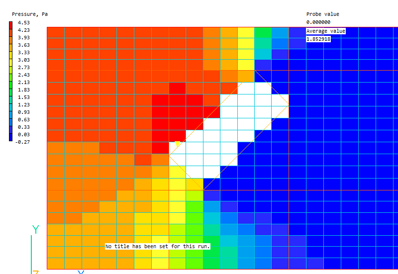
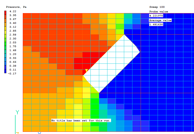
With contour averaging turned off, the Viewer displays the actual castellated representation of the surfaces. This is mitigated to some extent by modifications made to the cell face areas in the cells containing the fluid-solid interface, but it is still approximate.
If a cell-centre is covered by solid, that entire cell is treated as blocked. Sparsol can handle thin objects because it recognises that the link is cut, so will prevent flow in the cut direction.
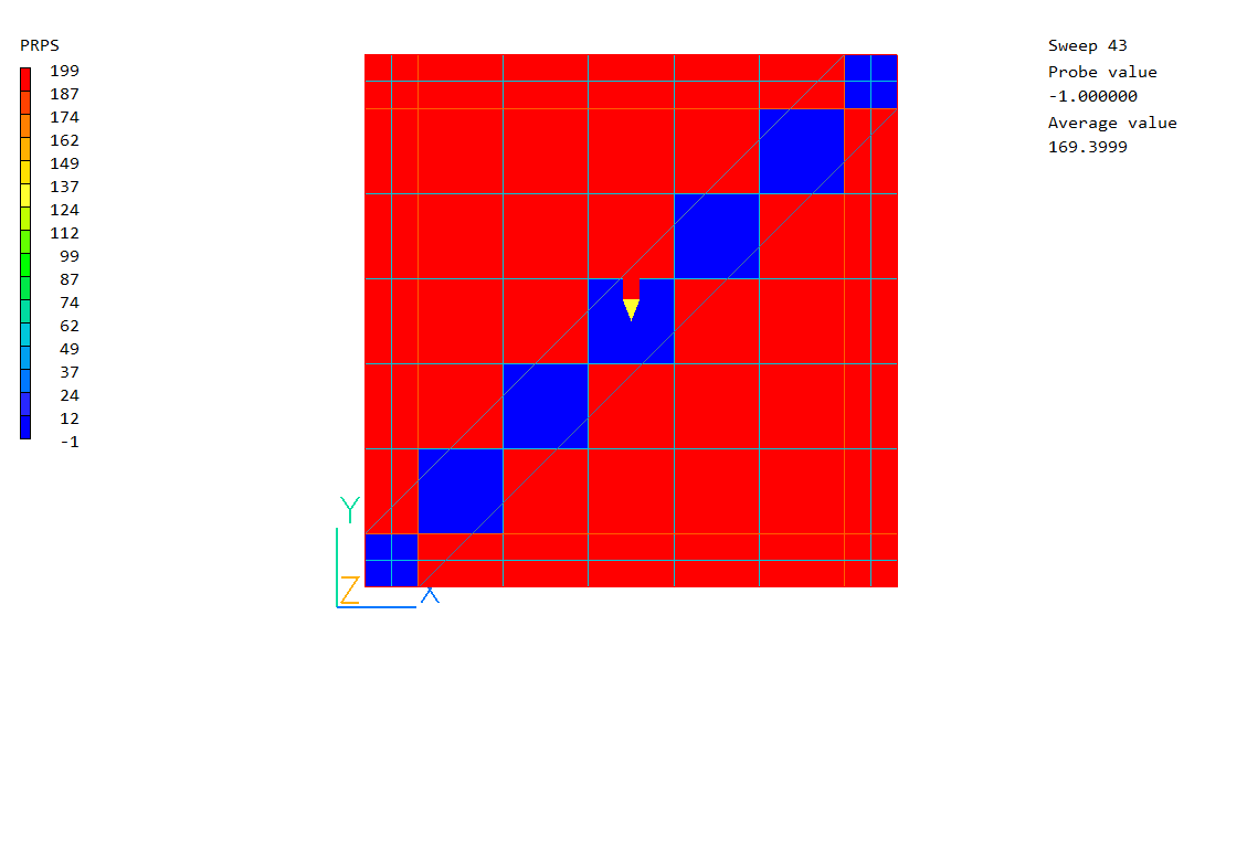
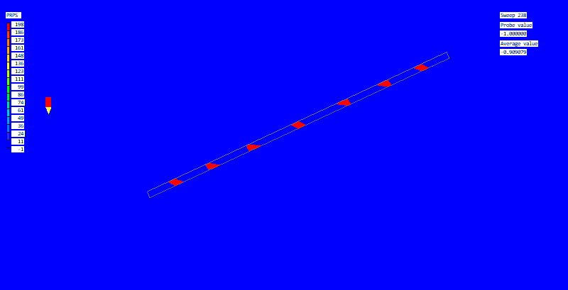
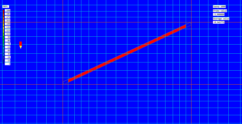
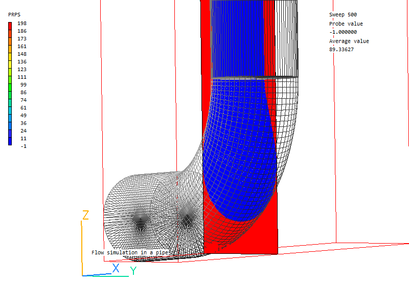
Sparsol is also not good at dealing with thin channels. Although the averaged PRPS field may look OK,

when the averaging is turned off it is clear that there is no path for fluid to pass through:
Parsol
This method of dealing with faceted objects is an alternative to Sparsol, and is to be preferred when the details of the flow adjacent to the blockages are very important. It is activated by the settings
ISG62=0; PARSOL=T
in Group 19 of Q1, or by selecting 'PARSOL' from the 'Cut-cell method' box of the Grid Mesh Settings dialog.
Parsol calculates the intersections of the cell-edge grid lines with the geometry, and divides the cell into two parts, one fluid and one solid. The definition of the surface is better than in Sparsol, but it does not handle thin objects well, as it only considers two parts to a cut cell.
Advantages
- Cut cells represent sloping / curved surfaces more accurately.
The shape of the cells containing the fluid-solid interface does not change with contour averaging on/off, as the cut cells are represented in the model as drawn.
The treatment of thin channels is better, as cells are only partially blocked:
However, as PARSOL can only deal with one solid and one fluid part the representation is still not perfect.
Disadvantages
- PARSOL on it's own cannot detect or handle objects thinner than the local grid. For the thin plate shown earlier, detection is
very poor, as only cells which are divided into two parts, or where the plate covers the cell centre are detected as having been affected:
Parsol - Double Cut
Recent work has been aimed at removing this restriction, and allowing for a cell to have two fluid and one solid, or two solid and one fluid part. The new extension to PARSOL is activated by:
ISG62=0; PARSOL=T; LSG4=T
in Group 19 of Q1, or by selecting 'PARSOL' from the 'Cut-cell method' box of the Grid Mesh Settings dialog, then 'Double-cut dell detection from the 'Settings' dialog.
The channel is now shown correctly:
OldParsol
This is the previous (pre PHOENICS 2019) version of Parsol. It is retained temporarily for customers wishing to preserve backward compatibility. It will be withdrawn at some stage. It is activated by:
ISG62=0; ISG60 = 1; PARSOL=T
in Group 19 of Q1, or by selecting 'Old-PARSOL' from the 'Cut-cell method' box of the Grid Mesh Settings dialog.
Advantages
- None
Disadvantages
- The detection of blockages is poorer than with Parsol:

Detection with OldParsol
Detection with Parsol.
How cut-cell edges are detected
The 2D-Section Method (2DSM) is a reliable method of detecting the intersections of the facets defining the object with the grid lines. For this reason it is used in three all three versions - SParsol, Parsol and OldParsol.
The calculation of the intersection coordinates in the first two differs only in where the grid lines are. In the first, they pass through the centers of the cells. In the second, they pass through the cell edges. The OldParsol feature, unlike the previous ones, uses a specially adapted version of 2DSM.
The 2DSM proceeds as follows:
- The object intersection is detected plane by plane. Preliminary selection is used to make sure the detection is applied only to those facets which could possibly intersect with
the plane by checking the dimensions of the bounding box of the object in question.
- The intersection between a plane and a facet edge is a segment with start and end points. The segment complies with the 'in-on-the-right' convention, which means the right side of
the segment is in the object. The facet is slightly extended to avoid missing an intersection when the plane just touches the facet.
- Once all the segments within the plane are obtained together with the indications of whether the left side is fluid and the right side is solid, or vice versa, the intersections between
grid lines and segments are calculated. A slight extension is also used to avoid missing an intersection, e.g. the line just touches the end of the segment, which could lead to objects
missing in a column of cells.
The further use of the calculated intersection coordinates is different for these features.
OldParsol (pre PHOENICS 2019)
After reading all facets of the current object OldParsol detects the cut-cells by means of consideration the fluid edge fractions of twelve edges of each cell inside the current object and calculates the cut-cell geometry. This is done for each object in such a way that the settings of the last object have the highest priority.
Parsol (PHOENICS 2019 and newer)
In contrast, Parsol considers objects more closely.
It sorts all calculated intersections in a special way and sets for each object its own rank, which determines the priority in the processing of overlapping objects.
- Each grid line coincides with the edges of four columns of cells.
The edge may be classified in three ways:
- if the edge is wholly within a pair of intersection points, it means the edge is inside the object;
- if it is outside the pair of intersection points, the edge is in fluid;
- if one of the paired points falls on the edge, then the edge is cut.
The edge fraction is then used to indicate which case is in question for each edge.
- Consequently, the cells are divided into three groups:
- a cell with all twelve edges inside fluid is an open cell;
- a cell with all twelve edges inside the object is a blocked cell; and
- a cell with edges partly in object and partly in fluid is a cut cell, which is split into a fluid sub-cell and a blocked (solid) sub-cell.
- Then the necessary number of cut-cell geometry quantities, including centre coordinates, areas and volumes of sub-cells, etc, are calculated and stored in the PHOENICS F-array, and used by the PARSOL solver.
SParsol
The processing of the calculated intersections differs significantly for SParsol since it does not take into account the intersections of the cell edges, but it considers the intersections of the 'links' between the cell centers.
- It also sorts all calculated intersections of the links in a special way
and sets the number of the rank for each object.
- Then it considers intersections of all links in each direction and sets the
material numbers in the cells inside objects.
- After that, the geometric parameters of cells near blockage objects along cut-links are modified such as the cell face areas, the cut plane area, the normal vector, etc. No additional cut-cell storage locations are created.