Author: G.W. Michel
Editor: D.B. Spalding, J.C. Ludwig
Last updated: 23.06.08
The aim of the FacetFix program is to provide a means of examining and repairing files which describe solid bodies by way of triangular or quadrilateral facets, such as are provided by CAD packages, for example in STL (i.e. stereo-lithography) format.
The program was created because the CAD packages used by architects do not necessarily guarantee that the facets are consistent with each other in respect of inward- and outward-looking direction or define closed volumes.
PHOENICS requires that facets should have a direction sense in order that it can know on which side is the fluid and on which the solid; and of course facets which share an edge should be in agreement on the matter.
A further PHOENICS requirement is that the facets defining an object should, taken together, form a complete closed surface, such as is possessed by every solid body.
FacetFix takes in defective STL files, enforces consistency, adds facets so as to create complete surfaces, and produces the corresponding .dat files which are needed by the PHOENICS Virtual-Reality User Interface. It can do the same for defective .dat files also.
In many cases, the original STL file contains more than one closed surface - it may be the result of exporting several solid objects from the CAD package as a single file. FacetFix identifies each closed volume, and assigns it a different colour. It can also optionally output individual DAT (and STL) files for each closed volume. This allows the Earth solver to detect the objects more accurately, and the user to assign different properties and boundary conditions to each object.
This document describes:
Overview of program:
input - an STL or .dat file.
output 1 - a .dat file with all facets agreeing on orientation and holes in surfaces filled in.
output 2 - file with description of all the facets that were reversed, and list of holes filled in.
{optional outputs 3-n - repaired .dat and STL files for each individual closed volume. }
The 6 Major Steps in the Program
The description below covers the data formats used in FacetFix and the flow of the program during a run.
The FacetFix program can be accessed interactively. Clicking on 'Run, Utilities, FacetFix - STL repair' from the VR-Editor pull-down menu displays a simple dialog which can be used to control the FacetFix program.

The same dialog can be accessed from the command line (MSDOS prompt) by using the command runfacet. This presupposes that the PATH environment variable has been set using the /phoenics/d_utils/phoepath.bat file.
The top line defines the input file - either type the name into the box or use the 'Browse for Input' button to find the input file (stl or dat format) using standard file dialogs.
The second line chooses a filter file - the 'Browse for Filter file' option allows the user to search for a filter file using standard file dialogs.
The next 3 lines define a simple filter - give the minimum x,y,z and the maximum x,y,z coordinates to be considered. Facets falling outside this range will be excluded from the output file(s). Leaving these fields blank means that all facets in the input file will be processed. The 6 numbers define the range of the filter volume in the units of the stl file (often millimetres). Some prior knowledge of the size and positioning of objects is necessary to define the filter box correctly.
The sixth line sets the tolerance to be used. Vertices closer together than the tolerance times the domain size will be treated as identical. The user should choose the tolerance with consideration to the problem, but the default value is usually satisfactory for PHOENICS. Leave this field blank to use the default value.
The first part of the seventh line chooses whether to apply the 'exclude' option described in the filter section below. If left unticked, all facets which have at least one vertex with the filter box, or whose scope covers the filter box, will be included. If it is ticked, all vertices must fall inside the filter box for the facet to be included.
The second part gives a suitable output file name. If left blank FacetFix will choose a file name automatically, using the name of the input file and adding ' _0.dat' - e.g. building.stl becomes building_0.dat.
If the 'Multiple files' box on the end of the seventh line is ticked, an individual STL and .dat file will be output for each closed volume found in the original input file. If the output file name has been left as blank, FacetFix will use the default name with a sequence number added, in this example building_0_1.stl, building_0_2.stl etc. If a name has been given, the sequence number will be appended to that.
In addition, a file named 'outputfile'_0.stl is also created. This contains a single facet which sets the overall size of all the sub-objects. It can be used by the Editor to place all the sub-objects in their correct relative positions.
Once the files have been selected, the 'Run FacetFix' button at the bottom of the dialog launches facetfix.exe with arguments derived from the contents of the dialog window.
Optionally the user might want a filter file to define multiple sub-regions for extracting parts of the model (individual buildings etc). Rather than running repeatedly with different inputs in the filter box inputs, the sub-regions can be specified in a filter file.
Specify the filterfilename with the name (and path if necessary) of your filter file; if no filter file is specified and the filter box entries are blank, then all the facets in the model file will be used and mended. The filter file allows sections of the model to be output from the original data (perhaps a single building from a town).
Example 1:
runfacet with input file building.stl
will read the whole building.stl file, and correct facet direction and mend holes and output a single .dat file.
A large case with 1,400,000 facets takes about 1 minute on a 3GHz P4 machine.
Example 2:
runfacet with filter file filters, tolerance 0.0001 and input file building.stl
will extract buildings in areas specified in the file 'filters'. Any file name (without spaces in) is satisfactory - it is suggested that a name meaningful to the user with the extension '.fil' should be used. In the example if the domain of an object file is about 3000 metres long then the tolerance option will consider vertices closer than 0.3 metres to be identical.
The file is ascii. Comment lines start with a '*' ; Other lines define filter volumes - there is no limit to the number of filter volumes which may be specified other than disk space, memory size and cpu time!
Each filter defines a box consisting of 6 numbers (minimum X, max X, min Y, max Y, min Z, max Z) and some options.
There are currently 2 options:
Filter file example:
* Any comment will do - this is a sample filtering file
200000 250000 350000 450000 -5 100000 exclude output:hotel
300000.0 400000 320000 380000 -5.00 1.e6 output:gate
410000 450000 350000 450000 -5 100000
There are 3 filters here so the output will be 3 files of corrected facets. The 6 numbers define the range of the filter volume in the units of the stl file (often millimetres) - they must be separated by spaces but do not need to use any specific format (floating point or integer numbers are acceptable, the number of digits is not important).
The first example filter excludes any facet which is partially outside the filter; the other two include any facet whose extent includes the volume.
The first filter will produce a file called hotel.dat; the second 'gate.dat' and the third will derive a name from the STL file name (3dsite.stl will produce 3dsite_3.dat since this is the 3rd filter). Be aware that if the user has two filters with the same output: option then the first output file will be overwritten by the second.
Beware that if a filter is applied to a set of buildings, and the filter does not enclose a whole building then there will be significant holes in the building which may not be triangulated correctly (triangulation is only capable of mending small or nearly flat holes realistically).
Two examples are described here:
Buildings
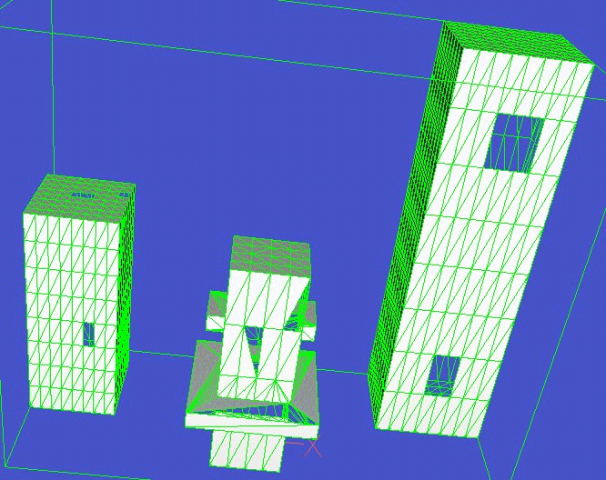
The buildings sample data is /phoenics/d_polis/d_docs/facetfix/building.stl , which when examined in AC3D appears as:

STL format Buildings before mending holes.
It clearly has several holes in the surface.
Run the facetfix program, and browse to the example file building.stl. Click 'Run FacetFix'.
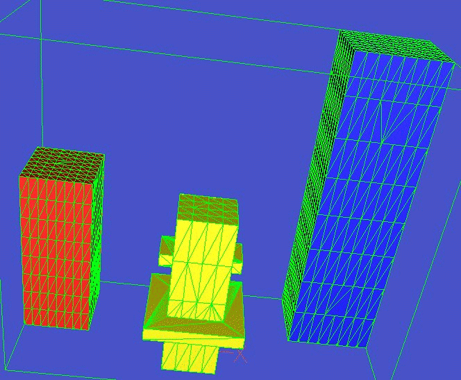
After a few seconds the file building_0.dat will be created in the local working directory. This can be compared with building.stl in VRE or AC3D.

Buildings with mended holes.
Making a half body from a car model
One of the files supplied with PHOENICS describes a motor vehicle (it is /phoenics/d_satell/d_object/public/deprecated/equipmt/wuaful.dat). This model describes a complete vehicle; often a half body is used in wind tunnel experiments (to allow a larger model within the limited size of the tunnel) and in CFD (to allow more resolution of detail with the same number of CFD cells and calculation time). This example shows how to use FacetFix to produce a half body from the wuaful car.
The car model has a centreline - that is there are facet edges all along the car half way across the vehicle. (If this were not so then dividing the car would require the model to be modified to produce such a centre line). The first 4 lines of the .dat file are:
* xpos,ypos,zpos,xsiz,ysiz,zsiz =
* 0.00000E+00 0.00000E+00 0.00000E+00 8.06000E-01 2.88000E-01 2.35290E-01
14214
0.00000E+00 5.00000E-01 8.17714E-02
showing that there are 14214 vertices in the model, and its origin is at (0,0,0) with lengths 0.806 by 0.288 by 0.23529. The coordinates in the rest of the .dat file are normalised to the range [0,1] (but converted to the specified sizes in the VR Editor and FacetFix).
The filter file (supplied as /phoenics/d_polis/d_docs/facetfix/halfcar.fil) which will extract one half of the body contains the line:
0 1 0 0.144 0 1 exclude output:wuahal
the range of x (0-1) and z (0-1) in the filter are not important, but must be larger than the range of coordinates of the model. The range of Y coordinate is half the width (0.288). Any facets partly outside the filter volume are ignored (this has no effect in this case since the facets meet precisely at the centreline Y=0.144). The output file is to be wuahal.dat (half the wua car). Alternatively the filter:
0 1 0.144 0.3 0 1 exclude output:wuahal2
could be used to extract the other half of the car. The maximum range of Y is not important provided it is at least as large as the maximum coordinate (0.288)
Run the program. Browse for the wuaful.dat file as input. Browse for the filter file halfcar.fil. Alternatively, enter 0 1 for Xmin Xmax, 0 0.144 for Ymin Ymax and 0 1 for Zmin Zmax. Tick the 'exclude' box. Enter wuahal as the output name. Click 'Run FacetFix'.
After about 30 seconds the file wuahal.dat will be created in the local working directory. This can be used directly in the VR Editor and becomes a blockage in EARTH. Usually the user will position the half model so that the centreline facets (which are created by facetfix) lie on the left or right boundary of the computational domain.
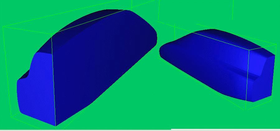
The figure shows two views of the half body created - the left image shows the cut through the centreline of the car, the right image the outside shape of the car.

Half Body of car.
NB with this example the original faceting makes it inappropriate to extract any portion of the car other than the half body based on the symmetry line, since some vertices of the facets within the part object will protrude beyond the filter range, resulting in a ragged hole and (although this will be filled by facetfix) the resulting shape will not resemble a slice through the vehicle.