Historically, tunnel ventilation systems were designed to maintain acceptable levels of pollutants. Oversizing usually resulted, as a consequence of the need to cope with congested traffic conditions, and this had the benefit that a satisfactory air flow could be maintained in the event of a fire. Now things have changed: vehicle emissions have reduced, safety has become more important and the energy costs associated with ventilation must be minimised. As a consequence, there is a need for much more precise design to ensure that smoke diffusion is controlled while people are evacuated from the tunnel. In particular, the control of back-layering phenomena represents a crucial factor in efficient design methodologies.
A number of experimental studies have been carried out and there is now the possibility of using the results to refine the simulation of tunnel flows in terms of air flow, temperature and smoke diffusion. Here, the PHOENICS CFD software is used to simulate the full-scale Memorial Tunnel Fire Ventilation Test Programme. The work was carried out by the University of Rome, in conjunction with ENEA - the Italian Agency for Energy, New Technology and the Environment.
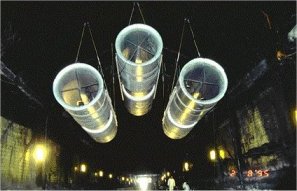
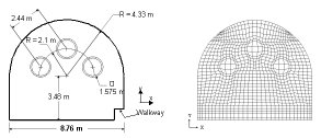
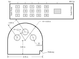
The Memorial Tunnel is a two-lane, 853m long, straight motorway gallery with a medium slope of 3.2% from north to south portal; the tunnel has a cross-section of 60.4m2. Various ventilation configurations were used for the experiments, but the simulations concentrate on the longitudinal system: 15 jet-fans were placed inside the tunnel, in groups of 3. The jet fans induced an air velocity of 34.2m/s and a mass flow rate of 43m3/s.
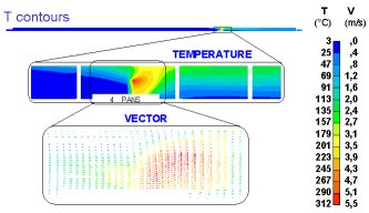
Fuel pans were placed about 240m from the south portal to simulate a fire, with a total heat release was about 10MW. Several tests were carried out, with various combinations of active fans.
A preliminary cold flow simulation was carried out to assess the code settings, such as wall roughness and swirl effects created by the fans. The calculated flow through the tunnel was about 10% below the measured value; this was acceptable, given the simplifications in the modeling and the uncertainty in the experimental set-up.
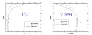
Fire simulations are often carried out without radiation modelling: the heat source associated with the fire is reduced to allow for the heat that is, in reality, transferred by radiation, but the detail of that heat transfer is ignored. In this case simulations were carried out both with and without radiation, making use of the IMMERSOL model in PHOENICS. Comparisons with data at monitoring locations showed that both approaches were able to predict the presence of a back-layering region near the ceiling, but only in the IMMERSOL case were the values in accordance with experiment. This aspect is of crucial relevance: a misrepresentation of the back-layering phenomenon in flows near the critical conditions could give a completely wrong prediction of the ventilation efficiency in controlling the smoke diffusion.
The simulations demonstrated the capability of the PHOENICS software to simulate tunnel fires and to predict the observed flow behaviour. This provides safety engineers with a powerful tool in the design of ventilation systems that will enhance safety while keeping down costs.